


21
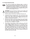
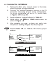
4.2 CALIBRATION PROCEDURE
1. Remove the front lens. Connect power to the meter,
observing proper wiring procedures.
2. Connect the precision resistance source to the P3
connector observing proper wiring configuration.
For 3Ðwire connections, use pins 1, 2, 3, and 4. Refer
to Figures 4-1 through 4-3.
3. Apply resistance input as indicated in Table 4-1.
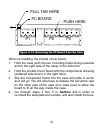
4. Adjust either the ZERO or SPAN potentiometer as
shown in Figure 4-4.
5. After adjusting the post, go back and verify both
temperature readings. Repeat step 4 as required.
Refer to Table 3-1 and Table 3-2 for internal jumper
settings.
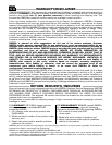
Figure 4-1. 2-Wire Configuration
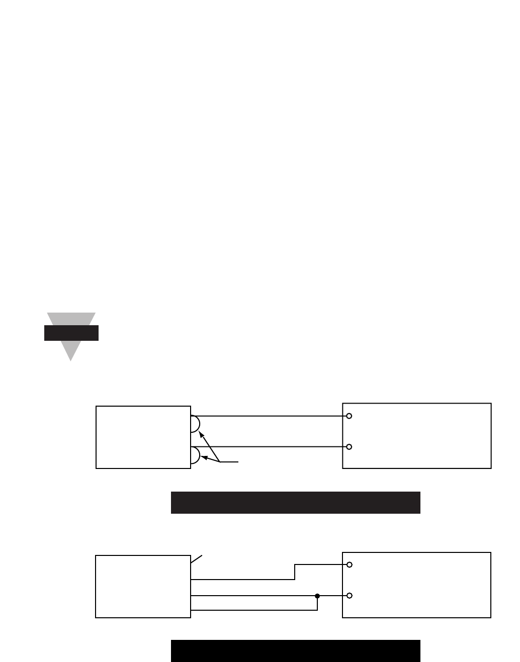
Figure 4-2. 3-Wire Configuration
BLACK
BLACK
NOT USED
RED
4
3
2
1
BLACK
RED
PRECISION
RESISTANCE
SOURCE
+ Excitation
Signal Hi
Signal Lo
- Excitation
P3
BLACK
JUMPER WIRE
(24 AWG)
RED
BLACK
RED
4
3
2
1
PRECISION
RESISTANCE
SOURCE
+ Excitation
Signal Hi
Signal Lo
- Excitation
P3
Note
☞