


4
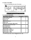
2.2 Back of the Meter
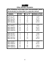
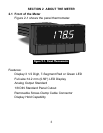
Figure 2-2 illustrates the rear of the meter.
Figure 2-2. Rear View Showing P1, P2, P3 Locations
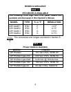
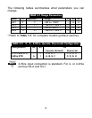
2.3 Connector Description
For RTD input wires, refer to Figure 3-3 thru 3-6.
Connector Description Connector PIN #
(AC) Earth Ground P1 1
(AC) Neutral P1 2
(AC) Line P1 3
(DC) -DC Return P1 1
(DC) +DC P1 2
(DC) No Connection (Not used) P1 3
Display Hold (Active Low) P2 1
Analog Return P2 2
Analog Output P2 3
RTD Input -EXC P3 1
RTD Input Signal Lo P3 2
RTD Input Signal Hi P3 3
RTD Input +EXC P3 4
P1 P2 P3
123 123
3412