


16
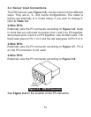
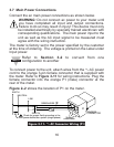
3.7 Main Power Connections
Connect the ac main power connections as shown below.
WARNING: Do not connect ac power to your meter until
you have completed all input and output connections.
Failure to do so may result in injury! This device must only
be installed electrically by specially trained electrician with
corresponding qualifications. The main power input to the
unit as well as the AC input signal to be measured must
agree with the wiring instruction.
The meter is factory set to the power specified by the customer
at the time of ordering. The voltage is printed on the Label under
Input power.
Refer to Section 3-2 to convert from one
configuration to another
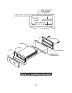
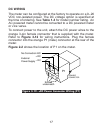
To connect power to the unit, attach wires from the ~AC power
cord to the orange 3-pin female connector that is supplied with
the meter. Refer to Figure 3-11 for wiring instructions. Plug the
female connector into the orange P1 (male) connector at the
rear of the meter.
Figure 2Ð2 shows the location of P1 on the meter.
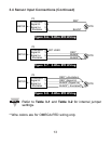
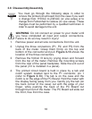
Figure 3-11. ~AC Connector Wiring (P1)
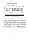
FUSE
GREEN WIRE
EARTH
Screws
underneath
ORANGE
CONNECTOR
P1
©
N
L
1
2
3
SWITCH
LINE
NEUTRAL
Check for proper Earth grounding in the
power distribution system (single phase).
Note
☞