


18
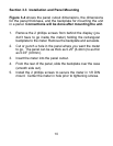
3.8 Disassembly/Assembly
You must go through the following steps in order to
remove the printed circuit board from the case if you want
to change from 115VAC to 230VAC (or vice versa) or to
change from Fahrenheit to Celsius (or vice versa). These
changes must be performed by a qualified technician in
order to avoid damage to the unit.
WARNING: Do not connect ac power to your meter until
you have completed all input and output connections.
Failure to do so may result in injury!
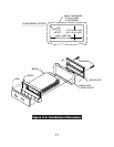
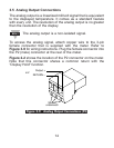
1. Remove power and all wire connections from the unit.
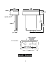
2. Unplug the three connectors (P1, P2, and P3) from the
back of the meter. Grasp them firmly on the top and
bottom of the connector and pull. Figure 3-13 shows the
location of the three connectors.
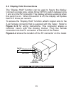
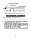
3. Remove the friction fit lens by prying down and forward
from the top of the meter. Remove the mounting screws
from the rear of the panel backplate. Slide the unit out of
the panel (if it is installed in a panel).
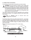
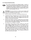
4. The printed circuit board is held in place by a tab and
notch system located next to the P1 connector, pin 1
(refer to Figure 3-13). The tab is on the case and the
notch is on the edge of the PC Board. Hold the meter with
the display facing away from you. Gently pry the tab (on
the back corner of the case) out with the edge of your
finger, while pushing the back of the PC Board out
through the front of the meter. The PC Board will slide out
the front, free from the case.
Note
☞