


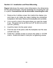

6
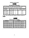
Voltage Jumper Pin Settings
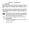
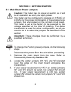
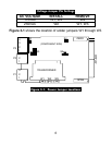
Figure 3-1 shows the location of solder jumpers W1 through W3.
Figure 3-1. Power Jumper Locations
P3
P1
W1 W2 W3
2
1
2
3
1
TRANSFORMER
SPAN
DISPLAY
ZERO
(COMPONENT SIDE)
P2
2
3
1
3
4
S2
S3
S4
S5
AC VOLTAGE INSTALL REMOVE
115VAC W1, W3 W2
230VAC W2 W1, W3