


5
SECTION 3 GETTING STARTED
3.1 Main Board Power Jumpers
Caution: The meter has no power-on switch, so it will
be in operation as soon you apply power.
The meter can be configured to operate on 115VAC or
230VAC by the proper combination of the soldered wire
jumpers that are located on the printed circuit board.
The meter is set at the factory to be powered by the
voltage specified at the time of ordering. The same
transformer is used for either configuration, so all you
need to do is to select the jumpers as described in this
section.
Important: These changes must be performed by a
qualified technician.
To change the Factory preset jumpers, do the following
steps:
Disconnect the power from the unit before proceeding.
1. Remove the main board from the case. Refer to
Disassembly/Assembly Section 3.8.
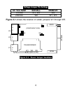
2. Locate the solder jumpers W1, W2, and W3 (located
near the edge of the main board alongside the
transformer).
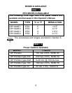
3. If your power requirement is 115 V ac, solder jumpers
W1 and W3 should be wired, but jumper W2 should
not. If your power requirement is 230 Vac, solder
jumper W2 should be wired, but jumpers W1 and W3
should not.
Note
☞