


9
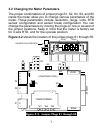
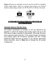
Figure 3-3 gives an example of how to set S4 and S5 to configure
a MF1 meter option. There is a jumper plug across A on S4 and
another jumper plug across A on S5. B and C on S5 are not used.
Figure 3-3. Example of How to Set Meter Option MF1
(jumpers S4 and S5)
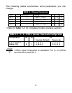
SENSOR BREAK PROTECTION:
The proper combination of jumpers on S3 will determine the
direction in which the display and analog output will go if the
RTD sensor breaks (upscale or downscale). The meter is factory
set to upscale break protection. If the sensor breaks, the display
and analog signal will increment (upscale) and the 3 least
significant digits will then go blank. If you require downscale
break protection, refer to Table 3-2 to change the S3 jumper
configuration.
AC
B
S4 S5
JUMPER PLUG
COVERING BOTH PINS
JUMPER PLUG
COVERING
TWO PINS
OVER "A"
A