


31
E
L
E
C
T
R
O
N
I
C
S
PROCEDURE 6ELECTRONICS
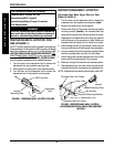
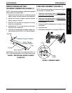
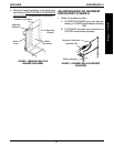
REPOSITIONING BATTERY
CHARGER CONNECTOR (FIGURE 3)
NOTE: This procedure applies to wheelchairs equipped
with the Mark IV controller ONLY.
1. Remove the hex bolt from the T-nut that secures the
battery charger connector bracket to the wheelchair.
2. Remove the battery charger connector bracket/
battery charger connector.
3. Slide the T-nut out from the channel on the base
frame of the wheelchair.
4. Reposition the T-nut in the channel on the oppo-
site side of the wheelchair.
5. Install the hex bolt through the battery charger con-
nector bracket AND into the T-nut. Securely tighten.
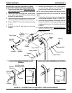
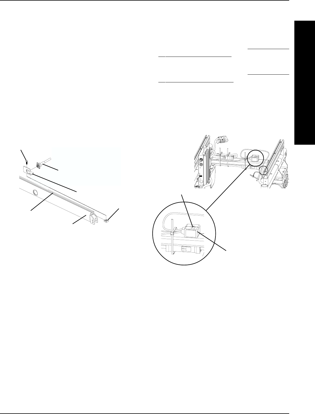
FIGURE 3 - REPOSITIONING BATTERY CHARGER
CONNECTOR
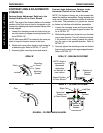
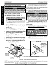
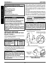
FIGURE 4 - FUSE REPLACEMENT
Fuse
Fuse
Holder
Battery Charger Connector
Base Frame
Hex Bolt
FUSE REPLACEMENT (FIGURE 4)
NOTE: This procedure applies to wheelchairs equipped
with the Mark IV controller ONLY.
1. Remove the front shroud. Refer to REMOVING/IN-
STALLING THE SHROUDS in PROCEDURE 9 of
this manual.
2. Remove the front battery. Refer to
REMOVING/IN-
STALLING THE BATTERIES in PROCEDURE 11
of this manual.
3. Grasp and pull the existing fuse to remove it from
fuse holder.
4. Install new fuse.
5. Reassemble wheelchair by reversing STEPS 1-2.
Channel
Battery Charger
Connector Bracket
T-Nut
NOTE: Base frame shown is for reference ONLY. It is
NOT a true representation of the Pronto base frame.