


30
This Procedure Includes the Following:
Preparing MKIV Joystick for Use
Repositioning MKIV Joystick
Repositioning Battery Charger Connector
Fuse Replacement
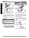
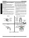
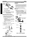
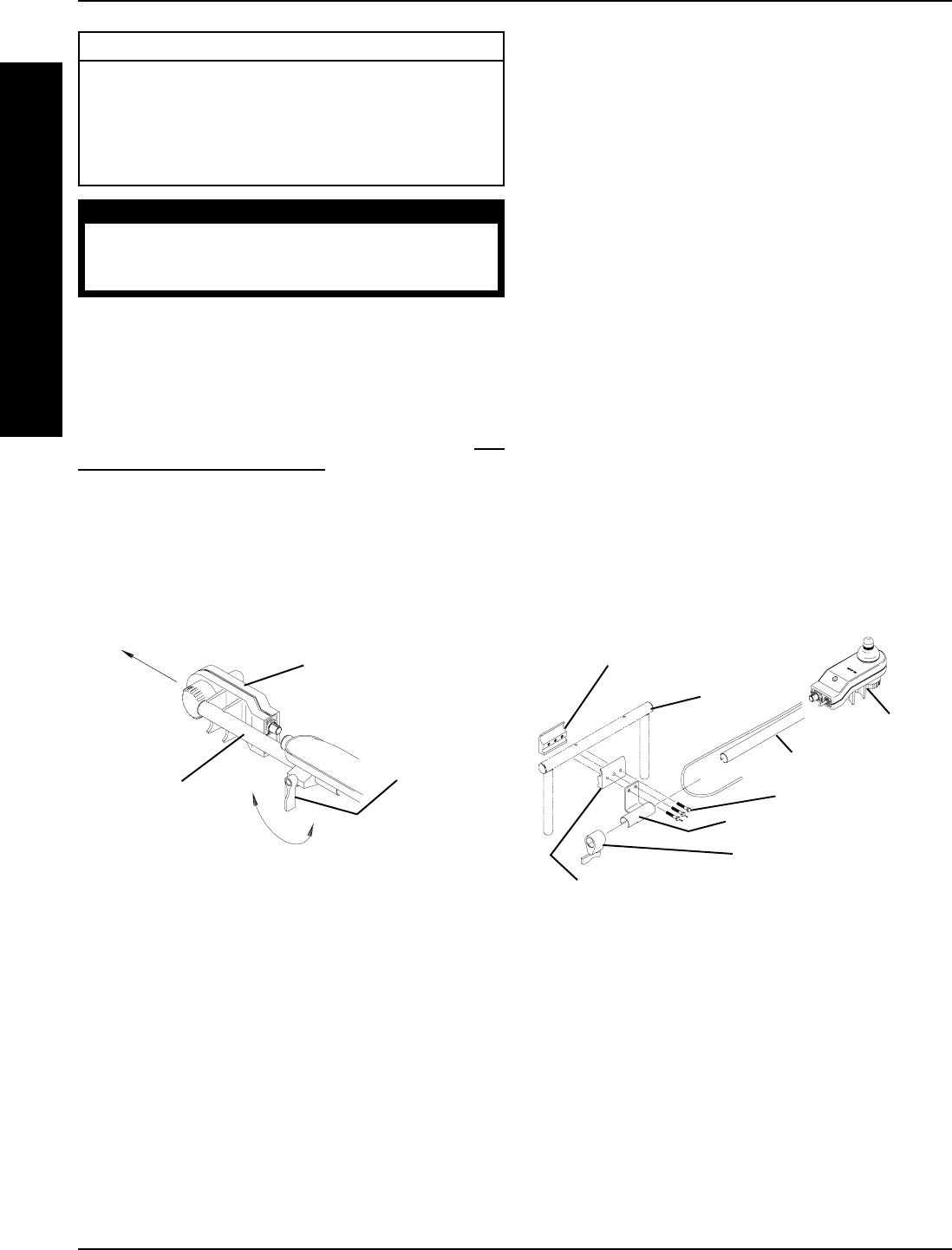
PREPARING MKIV JOYSTICK FOR
USE (FIGURE 1)
NOTE: The MKIV joystick is factory installed on the right side
of the wheelchair. To reposition the MKIV joystick onto the left
side of the wheelchair, perform one (1) of the following: AD-
JUSTABLE SEAT BACK ANGLE/RECLINER SEAT -
RE-
POSITIONING MKIV JOYSTICK in this procedure of the
manual or CAPTAIN'S SEAT MODEL WHEELCHAIRS -
have the joystick repositioned by a qualified technician.
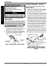
1. Turn the lever on the adjustment lock to release the
adjustment lock from joystick mounting tube.
2. Slide joystick mounting tube to the desired position.
3. Turn the lever on the adjustment lock to secure the
adjustment lock to the joystick mounting tube.
Joystick
MountingTube
FIGURE 1 - PREPARING MKIV JOYSTICK FOR USE
MKIV Joystick
Adjustment
Lock
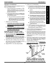
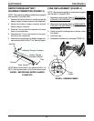
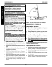
Threaded Hole Half Clamp
Joystick Mounting Tube
Hex Screws
Joystick Mounting Bracket
Adjustment Lock
Arm Tube
Joystick
Opened Hole Half Clamp
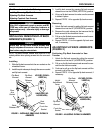
FIGURE 2 - REPOSITIONING MKIV JOYSTICK -
ADJUSTABLE SEAT BACK ANGLE/RECLINER SEAT
MODELS
WARNING
After ANY adjustments, repair or service and BEFORE
use, make sure all attaching hardware is tightened
securely - otherwise injury or damage may result.
E
L
E
C
T
R
O
N
I
C
S
PROCEDURE 6
REPOSITIONING MKIV JOYSTICK
Adjustable Seat Back Angle/Recliner Seat
Models (FIGURE 2)
1. Turn the lever on the adjustment lock to release the
adjustment lock from joystick mounting tube (tube).
2. Remove the joystick from the wheelchair.
3. Remove the three (3) hex screws that secure joystick
mounting bracket (bracket), the threaded hole half
clamp and the opened hole half clamp to the arm tube.
4. Reposition the threaded hole half clamp and opened
hole half clamp on the opposite arm tube. Make sure
threaded hole half clamp is on the inside of arm tube.
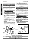
5. While holding the two (2) half clamps, install the front
hex screw into the two (2) half clamps. Securely tighten.
6. Line up mounting holes of the joystick mounting bracket
with the mounting holes in the two (2) half clamps.
7. Secure the joystick mounting bracket to the two (2) half
clamps with the remaining two (2) hex screws.
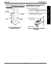
8. Slide tube through the bracket to the desired position.
9. Slide adjustment lock over end of tube and secure ad-
justment lock to tube by turning lever on adjustment lock.
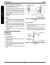
NOTE: If adjustment lock does not fit over tube, rotate 180
o
.