


26
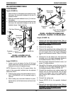
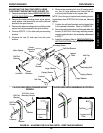
FOOTREST ANGLE ADJUSTMENTS
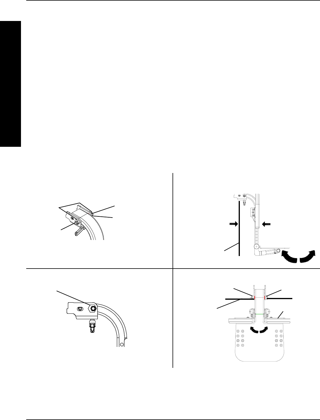
(FIGURE 23)
Footrest Angle Adjustment Relative to the
Vertical Position of the Front Shroud
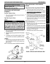
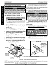
NOTE: The angle of the footrest relative to the vertical
position of the front shroud can be increased or de-
creased by adjusting both cams located at the top of the
footrest support.
1. Loosen the mounting screw and locknut that se-
cure the cams to the upper mounting bracket. Re-
fer to DETAIL “B”.
NOTE: Both cams MUST be rotated to the same po-
sition to keep the footrest square to the base.
2. Rotate both cams either direction until footrest is
at desired angle. Refer to DETAIL “C” and “D”
3. Securely tighten mounting screw and locknut.
FIGURE 23 - FOOTREST ANGLE ADJUSTMENTS
DETAIL “E” - TOP VIEW OF FOOTREST
DETAIL “D” - SIDE VIEW OF FOOTRESTDETAIL “B”
Right Cam
Left Cam
Footrest
Horizontal
Position
of Front Shroud
Direction of
Footrest
Rotation
DETAIL “C”
Mounting
Screw
Locknut
Cams
Upper
Mounting
Bracket
Vertical Position
of Front Shroud
NOTE: Angle is
increased or
decreased
depending
on direction of
cam rotation
Direction of
Footrest
Rotation
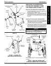
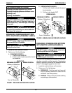
Footrest Angle Adjustment Relative to the
Horizontal Position of the Front Shroud
NOTE: The footrest is factory set to be centered be-
tween the stabilizer assemblies. During shipping and
daily use the footrest can become shifted to one side
or the other. This procedure is to center the footrest
so it does not interfere with stabilizer assemblies
1. Loosen the mounting screw and locknut that se-
cure the cams to the upper support bracket. Re-
fer to DETAIL “B”.
2. While holding either cam in position, turn the other
cam in one direction. This will rotate the footrest.
If the footrest is not rotating towards the center,
turn the cam in the opposite direction. Refer to
DETAIL “E”.
3. Securely tighten the mounting screw and locknut
that secure the cams to the upper support bracket.
Refer to DETAIL “B”.
Cam
F
R
O
N
T
R
I
G
G
I
N
G
S
FRONT RIGGINGSPROCEDURE 3