


20
F
R
O
N
T
R
I
G
G
I
N
G
S
FRONT RIGGINGSPROCEDURE 3
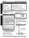
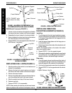
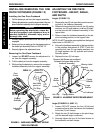
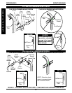
FIGURE 12 - INSTALLING/REMOVING THE ONE
PIECE FOOTBOARD
Legrest
Tube
Support
Assembly
Adjustment
Lever
Seat
Frame
Pull
Ring
Detent Pin
Assembly
DETAIL “A”
Hex Head
portion of
Pull Ring
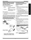
ADJUSTING THE ONE PIECE
FOOTBOARD - HEIGHT, ANGLE,
AND DEPTH
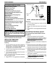
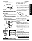
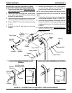
Height (FIGURE 13)
1. Remove the two (2) hub caps that cover the mount-
ing bolt of the footboard assembly.
2. Remove the mounting bolt, locknut, two (2) caplug
washers, two (2) large washers, and two (2) spac-
ers that secure the footboard assembly to the
legrest tube.
3. Raise or lower the footboard assembly to the de-
sired mounting position on the legrest tube.
NOTE: Do NOT cover the warning label on the legrest
tube shown in FIGURE 13.
4. Secure the footboard assembly to the legrest tube
in the position determined in STEP 3 with the
mounting bolt, two (2) cap caplug washers, two
(2) large washers, two (2) spacers and locknut.
Securely tighten.
5. Replace the two (2) hub caps.
FIGURE 13 - ADJUSTING THE FOOTBOARD HEIGHT
Caplug Washer
Locknut
Large
Washer
Caplug
Washer
Mounting
Bolt
Large
Washer
Hub Cap
Hub Cap
Footboard
Spacers (Not Shown are positioned
between the legrest tube and the
footboard assembly.)
Warning Label
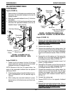
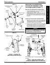
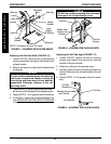
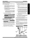
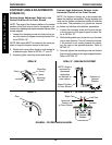
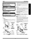
Angle (FIGURES 14 AND 15)
1. Loosen, DO NOT remove, the four (4) flat head
screws and barrel nuts that secure the footboard
to the two (2) half clamps.
2. Rotate the two (2) half clamps on the pivot hinge
until the desired angle is achieved.
3. Securely tighten the four (4) flat head screws to
the footboard and half clamps.
INSTALLING/REMOVING THE ONE
PIECE FOOTBOARD (FIGURE 12)
Installing the One Piece Footboard
1. Pull the detent pin out from the support assembly.
2. While pulling detent pin, insert the legrest tube of the one
piece footboard assembly into the support assembly.
WARNING
Before operating the wheelchair, ensure de-
tent pin is engaged, and adjustment lever is
securely tightened, otherwise, injury and/or
damage may result.
3. Visually inspect and ensure that the detent pin is
engaged.
4. Ensure pull ring is resting on the hex head portion of
the detent pin assembly. Refer to DETAIL “A”.
5. Securely tighten the adjustment lever.
Removing the One Piece Footboard
1. Loosen, but DO NOT remove, the adjustment le-
ver from the support assembly.
2. Pull the detent pin from the support assembly.
3. While pulling the detent pin, remove the one piece
footboard assembly from the support assembly.