


A4 52 Part No. 1110545
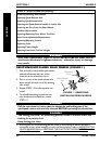
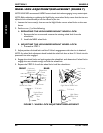
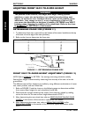
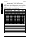
FIGURE 11 - DETERMINING FRAME SIZE
Seat Upholstery
Seat Rail
Bottom of Caster
Headtube
LENGTH
(INCHES)
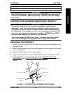
ADJUSTING FRONT SEAT-TO-FLOOR HEIGHT
WARNING
The position of the footrest, seat angle, back angle, seating system/
upholstery, caster size and position, rear wheel size and position, anti-
tippers, as well as the user condition directly relate to the stability of the
wheelchair. Any change to one (1) or any combination of the ten (10)
may cause the wheelchair to decrease in stability. EXTREME care MUST
be taken when changing the stability of the wheelchair. Refer to the chart
in STABILITY in SECTION 1 of this manual.
DETERMINING FRAME SIZE (FIGURE 11)
1. To determine frame size, measure from the bottom of the caster headtube to the top
of the seat rail at the edge of the seat upholstery.
2. Refer to the chart to determine the frame size.
LENGTH (INCHES) FRAME SIZE
11 17
12 18
13 19
14 20
15 21
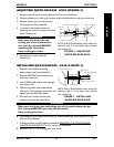
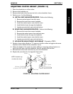
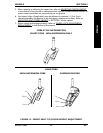
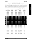
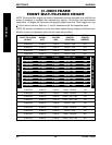
FRONT SEAT-TO-FLOOR HEIGHT ADJUSTMENT (FIGURE 12)
NOTE: Refer to STABILITY in SECTION 1 for warnings concerning wheelchair stability.
Seat-to-floor height is determined by measuring from the top of the seat rail to the
ground/floor.
The different seat-to-floor heights are possible by using different combinations of caster
size, caster position, and rear wheel size.
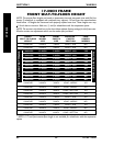
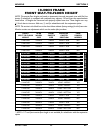
1. Refer to FIGURE 12 and the charts on the following pages to determine available
front seat-to-floor heights for each wheelchair frame size.
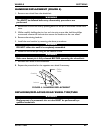
2. Determine the changes needed to the casters, forks and rear wheels by reading
across the chart for the seat-to-floor height determined in STEP 1.
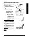
3. After determining the rear wheel size, refer to REMOVING/INSTALLING REAR
WHEELS in this section of the manual to replace the rear wheels.
4. After determining the caster size, refer to REPLACING CASTERS and/or
REPLACING FORKS in this section of the manual to replace the casters and/or
forks.
WHEELS
WHEELS
SECTION 5