


Part No. 1110545 41 A4
SECTION 4
FRAME
FRAME
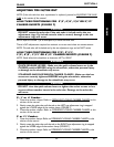
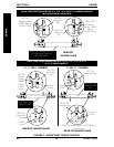
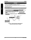
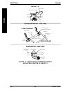
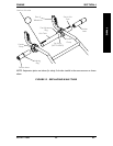
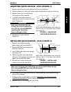
FIGURE 11 - ADJUSTING WHEELBASE WIDTH
ADJUSTING WHEELBASE WIDTH
(FIGURE 11)
NOTE: Perform this procedure on one (1) side of the wheelchair at a time for ease of adjustment.
1. Open the camber clamp. Refer to OPENING/CLOSING CAMBER CLAMPS in this
procedure of the manual.
WARNING
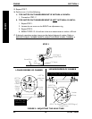
NEVER position the camber inserts in the axle tube with more than 3-inches
(12 indexing marks showing) of the camber insert outside of the axle tube.
Otherwise, the camber inserts will not be securely tightened in the axle tube
resulting in possible injury to the user or damage to the wheelchair.
2. Position the camber insert to the desired position. Make sure there are no more than
3-inches (12 indexing marks showing) of the camber inserts outside of the axle tube.
3. Slide the indexing ring on the camber insert until it is flush with the camber clamp.
NOTE: Before using the wheelchair, make sure both camber inserts are set at the same indexing
mark. This will make sure the distance between the rear wheel and the wheelchair is the same on
both sides.
WARNING
QUICK-RELEASE LEVERS - Make sure the quick-release levers are in the
CLOSED position BEFORE using the wheelchair, otherwise personal injury
or damage to the wheelchair may occur.
STANDARD AND SUSPENSION CAMBER CLAMPS - Make sure the hex
screws are securely tightened BEFORE using the wheelchair, otherwise
personal injury or damage to the wheelchair may occur.
CAUTION
DO NOT close the quick-release levers or tighten the socket screws or hex screws
without camber inserts in the axle tube. Damage to the axle tube will occur.
4. Close the camber clamp. Refer to OPENING/CLOSING CAMBER CLAMPS in this
procedure of the manual.
5. Repeat STEPS 1-4 for the opposite side of the wheelchair.
Indexing Ring
Axle Tube
Camber
Clamp
Indexing Marks
Camber
Insert
Camber
Insert