


A4 28 Part No. 1110545
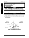
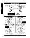
REPLACING SEAT FRAME (FIGURE 4)
1. Remove the rear wheels from the wheelchair. Refer to REMOVING/INSTALLING
REAR WHEELS in SECTION 5 of the manual.
2. Remove the seat upholstery from the wheelchair. Refer to
SEAT UPHOLSTERY
REPLACEMENT in SECTION 3 of the manual.
3. Remove the wheel locks from the wheelchair. Refer to WHEEL LOCK
ADJUSTMENT/REPLACEMENT in SECTION 5 of this manual.
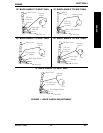
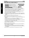
4. Note the installation position of the rear seat frame for proper reinstallation.
5. Remove the locknut, nylon washer and screw securing each side of the REAR seat
frame to the wheelchair frame as shown in DETAIL "A" of FIGURE 4.
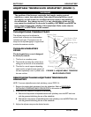
6. Remove two (2) allen screws and washers that secure FRONT seat frame to the
wheelchair front frame as shown in DETAIL "B" of FIGURE 4.
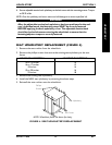
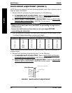
7. Remove the locknut, two (2) washers, stop and bolt from the REAR of the seat
frame as shown in DETAIL "C" of FIGURE 4.
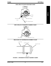
8. Remove the locknut, washer, coved spacer, nylon spacer, washer and bolt securing
the FRONT of the back angle bracket to the seat frame as shown in DETAIL "C" of
FIGURE 4.
9. Repeat STEPS 7-8 for the opposite side of the wheelchair.
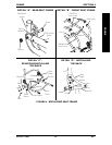
10. Remove the back canes with back angle brackets from the seat frame.
11. Align FRONT of seat frame with wheelchair front frame as shown in DETAIL "B" of
FIGURE 4.
12. Install two (2) allen screws and locknuts to secure FRONT of seat frame to
wheelchair front frame as shown in DETAIL "B" of FIGURE 4.
13. Install the screw, nylon washer and locknut to secure the REAR of the seat frame to
the wheelchair frame in the position noted in STEP 4.
14. Install the bolt, stop, two (2) washers and locknut onto the rear of the seat frame as
shown in DETAIL "C" of FIGURE 4.
15. Repeat for opposite side of the wheelchair.
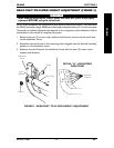
16. Align the latches on the back angle brackets with the stops installed in STEP 14 as
shown in DETAIL "D" of FIGURE 4.
17. Secure the FRONT of the back angle brackets to the seat frame with the bolts,
washers, nylon spacers, coved spacers, washers and locknuts as shown in DETAIL
"C" of FIGURE 4.
18. Reverse STEPS 1-3 to install wheel locks, seat upholstery and rear wheels.
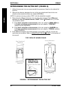
SECTION 4 FRAME
FRAME