


A4 24 Part No. 1110545
SECTION 4 FRAME
FRAME
Section 4 - Frame includes the following:
Back Angle Adjustment
Back Height Adjustment
Rear Seat-to-Floor Height Adjustment
Replacing Seat Frame
Opening/Closing Camber Clamps
Determining Toe in/Toe out
Adjusting Toe in/Toe out
Adjusting the Axle Tube
Repositioning Camber Inserts (Adjusting Rear Wheel Camber)
Adjusting Wheelbase Length (Adjusting Center of Gravity)
Adjusting Wheelbase Width
Replacing Axle Tube
WARNING
After ANY adjustments, repair or service and BEFORE use, make sure all
attachment hardware is tightened securely - otherwise, injury or damage
may result.
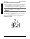
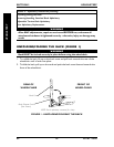
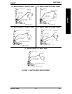
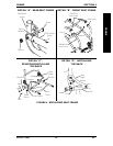
BACK ANGLE ADJUSTMENT (FIGURE 1)
NOTE: Perform this procedure on both sides of the wheelchair at the same time.
1. Loosen, but DO NOT remove the locknuts and hex screws that secure the back
angle bracket to the seat rail and the back cane.
2. Loosen the TOP locknut and slide the TOP hex screw away from the back angle
bracket to adjust the cam.
3. Adjust back canes to back angle required.
4. Adjust cam to achieve desired position.
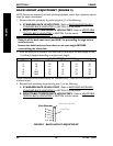
NOTE: An indexing notch has been put on the cam to help determine cam position for desired
back angle adjustment.
5. Secure cam in desired position. Torque all hex screws and locknuts to 960-1020
inch pounds (80-85 foot pounds).
NOTE: As shown in FIGURE 1, the adjustment cam can be rotated to several different positions
thus changing the overall back angle relative to the seat rail.