


50
NOTE: Make sure the number of threads showing
beyond the outside jam nut is the SAME for both rear
wheels. This will help avoid a "3-wheeling" situation.
7. Adjust the wheel locks. Refer to ADJUSTING THE
WHEEL LOCKS in PROCEDURE 7 of this manual.
8. If wheelchair is equipped with anti-tippers,
adjust to maintain proper clearance. Refer to AD-
JUSTING THE ANTI-TIPPERS in PROCEDURE 7
of this manual.
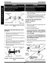
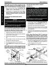
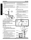
ADJUSTING THE WHEELBASE WIDTH
(FIGURE 9)
WARNING
The following procedure must be performed only
by an authorized Invacare Dealer or Qualified Tech-
nician.
After adjustments and before use make sure all at-
taching hardware is securely tightened.
NOTE: Increasing the wheelbase width may prevent
the wheelchair from passing through smaller door
jams and other tight places. Consider access to daily
activities before increasing wheelbase width.
1. Remove the rear wheel from the wheelchair.
2. Loosen the two (2) jam nuts that secure the axle bush-
ing to the axle mounting plate.
3. Move the axle bushing in or out to the desired posi-
tion.
4. Securely tighten the jam nuts that secure the axle
bushing to the axle mounting plate.
5. Reinstall the rear wheel onto the wheelchair.
6. Repeat STEPS 1-5 for the opposite side of the wheel-
chair.
NOTE: Make sure the number of threads showing
beyond the outside jam nut is the SAME for both rear
wheels. This will help avoid a "3-wheeling" situation.
PROCEDURE 6 REAR WHEELS
R
E
A
R
W
H
E
E
L
S
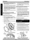
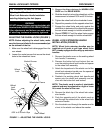
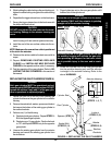
ADJUSTING REAR WHEEL HEIGHT
(FIGURE 10)
WARNING
The seat height, seat depth, back angle, seating sys-
tem, size and position of the rear wheels, as well as
the user condition directly relate to the stability of
the wheelchair. Any change to one (1) or any combi-
nation of the seven (7) may cause the wheelchair to
decrease in stability. These adjustments MUST be
performed by an authorized dealer or qualified tech-
nician.
After adjustments and before use make sure all at-
taching hardware is securely tightened.
1. Determine the rear wheel position for the desired seat-
to-floor height. Refer to CHANGING SEAT-TO-
FLOOR HEIGHT in PROCEDURE 9 of this manual.
2. Remove the rear wheels from the wheelchair.
3. Remove the four (4) hex screws, locknuts and eight
(8) coved washers that secure the axle mounting plate
to the wheelchair.
4. Position the axle mounting plate with the mount-
ing holes in the wheelchair frame determined in
STEP 1.
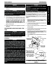
NOTE: Allegro Rigid Frame ONLY: To install axle
mounting plate into its' highest or lowest position,
one crossmember will use an axle plate mounting
hole. Install hex screw through the axle plate, coved
washer, wheelchair frame and the rigid crossmember.
5. Resecure the axle mounting plate to the wheelchair
frame. Refer to FIGURE 10 for correct hardware ori-
entation. Torque to 60-inch pounds.
6. Repeat STEPS 3-5 for the opposite side of the wheel-
chair.
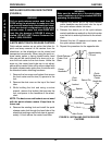
FIGURE 10 - ADJUSTING REAR WHEEL HEIGHT
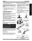
FIGURE 9 - ADJUSTING THE WHEELBASE WIDTH
Axle Bushing
Axle
Mounting
Plate
Jam Nuts
Coved
Washers
Axle Mounting Plate
Coved Washers
Washers
Hex Screws
Locknuts