


25
A
R
M
S
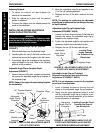
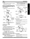
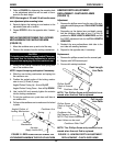
FIGURE 12 - REPLACING/REPOSITIONING THE
LOCKING MECHANISM IN THE FLIP-UP HALF ARM
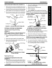
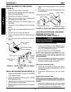
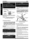
ARM PAD DEPTH ADJUSTMENT/
REPLACEMENT - CANTILEVER ARMS
(FIGURE 13)
Adjustment
1. Remove the phillips screw from the rear of the arm-
rest pad and self-taping screw if FULL LENGTH ARM
PADS.
2. Depending on the desired arm pad depth, reposi-
tion the cantilever slide tube to one (1) of five (5)
positions for DESK LENGTH ARM PADS and into
the FIRST adjustment hole for the FULL LENGTH
ARM PADS.
3. Reattach the arm pad/cantilever slide tube to the
arm tube with existing hardware.
4. Repeat for the opposite side, if necessary.
Replacement
1. Remove the phillips screws from the armrest pad.
2. Replace with NEW armrest pad.
3. Secure with existing hardware.
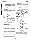
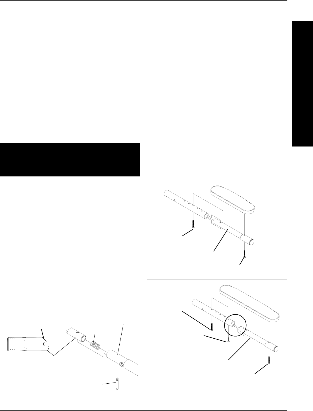
FIGURE 13 - ARM PAD DEPTH ADJUSTMENT/
REPLACEMENT - CANTILEVER ARMS
Phillips Screw
(Rear of Armrest
Pad)
Cantilever Arm
Self-Tapping Screw
Cantilever Slide Tube
NOTE: Only these Adjust-
ment Holes can be used.
NOTE: This Phillips Screw only needs to be re-
moved when Armrest Pad is replaced.
Full Length
Arm Pads
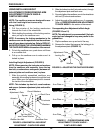
NOTE: This Phillips Screw only needs to be re-
moved when Armrest Pad is replaced.
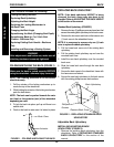
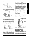
ARMS PROCEDURE 2
3. Refer to FIGURE 6 to determine the mounting hole
in the adjustment plate that will be used to corre-
spond to the back angle.
NOTE: Back angles of 105
o
and 110
o
will use the same
arm adjustment plate mounting holes.
4. Securely tighten the locking pin and washer to the
adjustment plate with a locknut.
5. Repeat STEPS 1-4 for the opposite side, if neces-
sary.
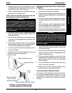
REPLACING/REPOSITIONING THE LOCKING
MECHANISM IN THE CANTILEVER ARM
(FIGURE 12)
1. Move the cantilever arm up and out of the way.
2. Remove the actuator from the locking mechanism.
CAUTION
The locking mechanism is spring loaded. Place your
free hand over the locking mechanism to prevent
the parts from springing out of the cantilever arm.
3. Slowly let the locking mechanism and spring slide
out of the cantilever arm.
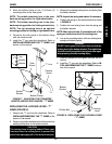
NOTE: Inspect the spring and replace if necessary.
4. Slide the new locking mechanism and spring into
the cantilever arm.
5. Position the angled portion of the locking mecha-
nism in one (1) of two (2) ways:
Angled Portion Facing Up - Arm will flip UP
Angled Portion Facing Down - Arm will flip DOWN
6. Use Loctite 242 and securely tighten the actuator
into the locking mechanism.
7. To lock the cantilever arm, push down until there is
an audible click.
8. Pull up on the cantilever arm to make sure it is locked
in place.
Angled Portion of
Locking Mechanism
Actuator
(Apply Loctite 242)
Locking
Mechanism
Cantilever Arm
Spring
Desk Length
Arm Pads
Phillips Screw
(Rear of Armrest
Pad)
Cantilever Slide Tube