


38
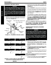
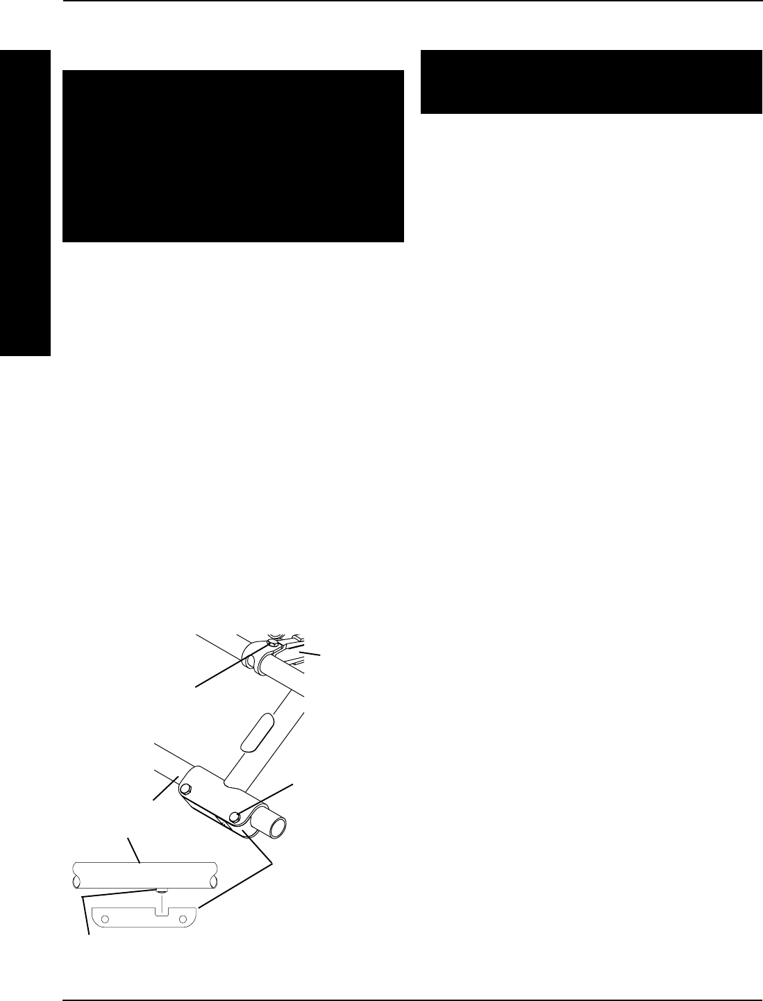
REPOSITIONING THE CROSSBRACES
(FIGURE 3)
WARNING
The seat height, seat depth, back angle, seating sys-
tem, size and position of the rear wheels, as well as
the user condition directly relate to the stability of
the wheelchair. Any change to one (1) or any combi-
nation of the seven (7) may cause the wheelchair to
decrease in stability. These adjustments MUST be
performed by an authorized dealer or qualified tech-
nician.
1. Determine the necessary self-tapping screw and
washer position for the desired seat depth of the
wheelchair. Refer to CHANGING SEAT DEPTHS in
PROCEDURE 10 of this manual.
2. Remove the hex bolts, locknuts and lower crossbrace
saddles that secure the bottom of the two (2)
crossbraces to the wheelchair frame.
3. Loosen, but do not remove the hex bolts and lock-
nuts that secure the two (2) pivot links to the wheel-
chair frame and crossbraces.
4. Reposition the self-tapping screw and washer to the
position determined in STEP 1.
5. Reverse STEPS 2-3 to reassemble wheelchair.
NOTE: If the wheelchair has become less stable af-
ter repositioning the self-tapping screw and washer
to the desired seat depth, reposition the rear wheels.
Refer to ADJUSTING THE WHEELBASE LENGTH in
PROCEDURE 6 of this manual.
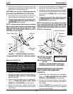
CHANGING SEAT WIDTH
WARNING
The following procedure must be performed by an
authorized Invacare dealer or qualified technician.
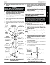
Standard Folding Frames (FIGURE 4)
1. Remove existing back and seat upholstery from the
wheelchair. Refer to REPLACING BACK UPHOL-
STERY in PROCEDURE 3 and REPLACING SEAT
UPHOLSTERY in this section of the manual.
NOTE: If adjusting the seat width of the wheelchair,
the back and seat upholstery MUST also be changed.
2. Remove the seat rails from the crossbraces. Refer
to CHANGING/REPOSITIONING SEAT RAILS in
this section of the manual.
3. Remove the hex bolts and locknuts that secure the
two (2) pivot links to the wheelchair frame and
crossbraces.
4. Remove the hex bolts, locknuts and lower crossbrace
saddles that secure the bottom of the two (2)
crossbraces to the wheelchair frame.
5. Remove the hex bolt, coved spacers, washers and
locknut that secure the two (2) existing crossbraces
together.
NOTE: Note orientation of coved spacer, washer and
locknut order for reinstallation.
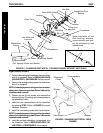
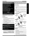
6. Assemble the two (2) new crossbraces together.
Refer to FIGURE 4 for hardware orientation.
7. Determine the mounting hole in the pivot link for the
corresponding seat width.
NOTE: Seat widths are stamped on the pivot link.
8. Reinstall the hex bolts and locknuts that secure the
pivot link to the wheelchair frame and crossbrace.
9. Reinstall the hex bolts, locknuts and crossbrace
saddles that secure the bottom of the two (2) new
crossbraces to the wheelchair frame.
NOTE: Position the crossbrace saddle on wheelchair
frame using the self tapping screw and washer on
the underside of wheelchair frame as reference. Re-
fer to FIGURE 4.
10. Reinstall the seat rails onto the crossbraces. Refer
to CHANGING/REPOSITIONING SEAT RAILS in
this section of the manual.
11. Install the new back and seat upholstery onto the
wheelchair. Refer to REPLACING BACK UPHOL-
STERY in PROCEDURE 3 and REPLACING SEAT
UPHOLSTERY in this section of the manual.
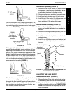
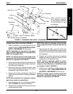
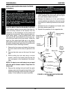
FIGURE 3 - REPOSITIONING THE CROSSBRACES
Hex Bolts and
Locknuts
Hex Bolts,
Loosen But Do
Not Remove
Pivot Links
Lower Crossbrace
Saddle
Wheelchair
Frame
PROCEDURE 4 SEAT
S
E
A
T
Self-Tapping Screw and Washer