


42
REPLACING/REPAIRING FRONT CASTER
TIRE/TUBE
WARNING
Replacement of front caster tire or tube MUST be
performed by an authorized Invacare dealer or
qualified technician.
CAUTION
As with any vehicle, the wheels and tires should
be checked periodically for cracks and wear, and
should be replaced when necessary.
90
o
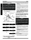
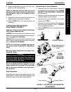
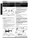
ADJUSTMENT OF THE CASTER
HEADTUBES
Whenever the seat height is raised or lowered by
changing the caster size, fork stem length, rear wheel
size or axle mounting plate adjustments, the caster
headtube needs to be checked to maintain a 90
o
angle
to the ground/floor. Caster headtubes that are per-
pendicular to the floor will roll better, track straighter
and minimize any "3-wheeling" of the wheelchair.
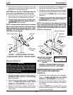
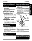
Inline Caster Headtubes (FIGURE 3)
1. Make sure the wheelchair is on a flat surface.
2. Loosen, but do not remove the bottom hex screw,
washer and locknut that secure the caster
headtube to the wheelchair frame.
3. Loosen, but do not remove the locknut and washer
that secure the adjustment cam to the caster
headtube.
4. Position a large right triangle or "L" square on the
flat surface and against the caster headtube.
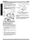
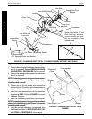
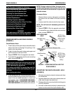
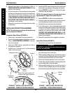
FIGURE 4 - OFFSET CASTER HEADTUBES
Caster Headtube
Adjustment Cam
Channel
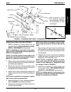
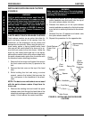
FIGURE 3 - INLINE CASTER HEADTUBES
"L" Square
Caster/Fork
Caster Headtube
5. Move the caster headtube back and forth until the
caster headtube is perpendicular to the ground/
floor.
6. While holding the caster headtube perpendicular
to the ground/floor, securely tighten the adjustment
cam to the caster headtube.
7. Make sure the caster headtube is still perpendicu-
lar to the ground/floor by placing the large right
triangle or "L" square on the flat surface and against
the caster headtube.
8. Securely tighten the hex bolt, washer and locknut
that secure the caster headtube to the wheelchair
frame.
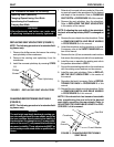
Offset Caster Headtubes (FIGURE 4)
1. Make sure the wheelchair is on a flat surface.
2. Loosen, but do not remove the bottom socket bolt,
washer and locknut that secure the caster
headtube to the wheelchair frame.
3. Remove the TOP washer and locknut that secure
the adjustment cam to the caster headtube.
4. Remove the adjustment cam from the caster
headtube.
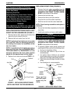
5. Position a large right triangle or "L" square on the
flat surface and against the caster headtube.
6. Move the caster headtube back and forth until the
caster headtube is perpendicular to the ground/
floor.
7. Reinstall the adjustment cam onto the TOP socket
screw that secures the adjustment cam to the
caster headtube.
Adjustment Cam
C
A
S
T
E
R
S
PROCEDURE 5 CASTERS
Caster/Fork
Caster Headtube
"L" Square