


24
USING/INSTALLING/HEIGHT
ADJUSTMENT/CORRESPONDING ARM
ADJUSTMENT TO BACK ANGLE -
CANTILEVER ARMS
NOTE: The cantilever arms are designed for use
with the fixed height back canes only.
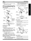
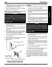
Using (FIGURE 9)
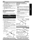
1. Pull the actuator of the locking mechanism
towards the front of the wheelchair.
2. While holding the actuator of the locking mecha-
nism, pull up on the cantilever arm.
NOTE: If necessary, the locking mechanism in the
cantilever arm can be repositioned so the cantilever
arm will open down instead of up. Refer to REPLAC-
ING/REPOSITIONING THE LOCKING MECHANISM IN
THE CANTILEVER ARM in this section of the manual.
3. To lock the cantilever arm, push down until there
is an audible click.
4. Pull up on the cantilever arm to make sure it is
locked in place.
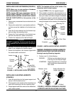
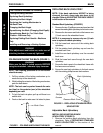
Installing/Height Adjustment (FIGURE 9)
NOTE: When removing the locknuts and washers
from the cantilever arm assembly, leave the top
hex bolt, coved washers and spacer (between ad-
justment plate and cantilever arm) in place.
1. Slide the partially assembled cantilever arm
assembly w/mounting hardware through the back
cane. Make sure the adjustment plate is towards
the inside of the wheelchair.
NOTE: This includes top hex bolt, coved washers
and spacer (between adjustment plate and cantile-
ver arm).
2. Slide the bottom hex bolt (w/coved washer) through
the adjustment plate and back cane.
3. Securely tighten the cantilever arm to the wheelchair
with two (2) locknuts and washers.
4. Adjust the angle of the cantilever arm, if necessary.
Refer to CORRESPONDING ARM ADJUSTMENT
TO BACK ANGLE in this section of the manual.
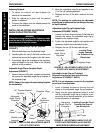
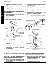
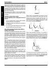
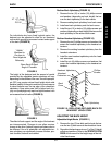
Corresponding Arm Adjustment to Back Angle
(FIGURES 10 and 11)
NOTE: This adjustment is recommended if the back
angle has been changed to keep arm parallel to the
ground/floor.
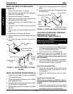
1. Flip the cantilever arm up and out of the way.
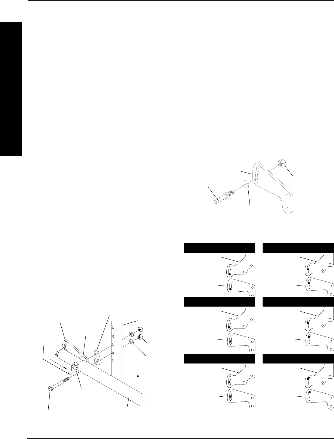
2. Remove the locknut that secures the locking pin to
the adjustment plate (FIGURE 10).
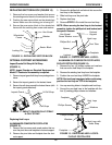
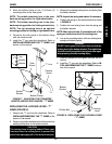
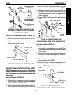
FIGURE 11 - CORRESPONDING ARM
ADJUSTMENT TO BACK ANGLE -
CANTILEVER ARMS
80
O
Back Plate
Arm Plate
85
O
Back Plate
Arm Plate
90
O
Back Plate
Arm Plate
100
O
Back Plate
Arm Plate
105
O
AND 110
O
Back Plate
Arm Plate
95
O
Back Plate
Arm Plate
A
R
M
S
ARMSPROCEDURE 2
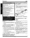
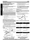
FIGURE 9- USING/INSTALLING/HEIGHT
ADJUSTMENT - CANTILEVER ARMS
Locknuts
Spacer
Actuator
Washers
Top Hex Bolt
and Coved Washer
Bottom Hex Bolt
Adjustment Plate
Back Cane
Coved Washers
Cantilever Arm
Adjustment Plate
Locking Pin
Locknut
Washer
FIGURE 10 - ADJUSTING THE CANTILEVER ARMS