8XC251SA, SB, SP, SQ USER’S MANUAL
5-12
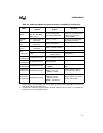
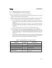
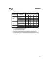
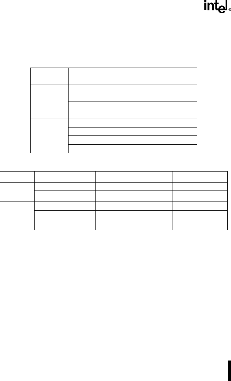
Table 5-7 lists the addressing modes for bit instructions and Table A-26 on page A-23 summarizes
the bit instructions. “Bit” denotes a bit that is addressed by a new instruction in the MCS 251 ar-
chitecture and “bit51” denotes a bit that is addressed by an instruction in the MCS 51 architecture.
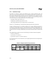
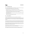
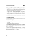
5.5 CONTROL INSTRUCTIONS
Control instructions—instructions that change program flow—include calls, returns, and condi-
tional and unconditional jumps (see Table A-27 on page A-24). Instead of executing the next in-
struction in the queue, the processor executes a target instruction. The control instruction provides
the address of a target instruction either implicitly, as in a return from a subroutine, or explicitly,
in the form of a relative, direct, or indirect address.
MCS 251 microcontrollers have a 24-bit program counter (PC), which allows a target instruction
to be anywhere in the 16-Mbyte address space. However, as discussed in this section, some con-
trol instructions restrict the target address to the current 2-Kbyte or 64-Kbyte address range by
allowing only the lowest 11 or lowest 16 bits of the program counter to change.
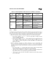
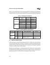
Table 5-6. Addressing Two Sample Bits
Location
Addressing
Mode
MCS
®
51
Architecture
MCS 251
Architecture
On-chip RAM
Register Name RAMREG.5 RAMREG.5
Register Address 23H.5 23H.5
Bit Name RAMBIT RAMBIT
Bit Address 1DH NA
SFR
Register Name TCON.2 TCON.2
Register Address 88.2H S:88.2H
Bit Name IT1 IT1
Bit Address 8A NA
Table 5-7. Addressing Modes for Bit Instructions
Architecture Variants Bit Address Memory/SFR Address Comments
MCS
®
251
Architecture
(bit)
Memory NA 20H.0
–7FH.7
SFR NA All defined SFRs
MCS 51
Architecture
(bit51)
Memory 00H–7FH 20H.0
–7FH.7
SFR 80H–F8H
XXH.0–XXH.7, where XX = 80,
88, 90, 98, ..., F0, F8.
SFRs are not defined
at all bit-addressable
locations.


