8XC251SA, SB, SP, SQ USER’S MANUAL
C-10
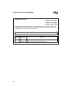
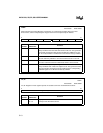
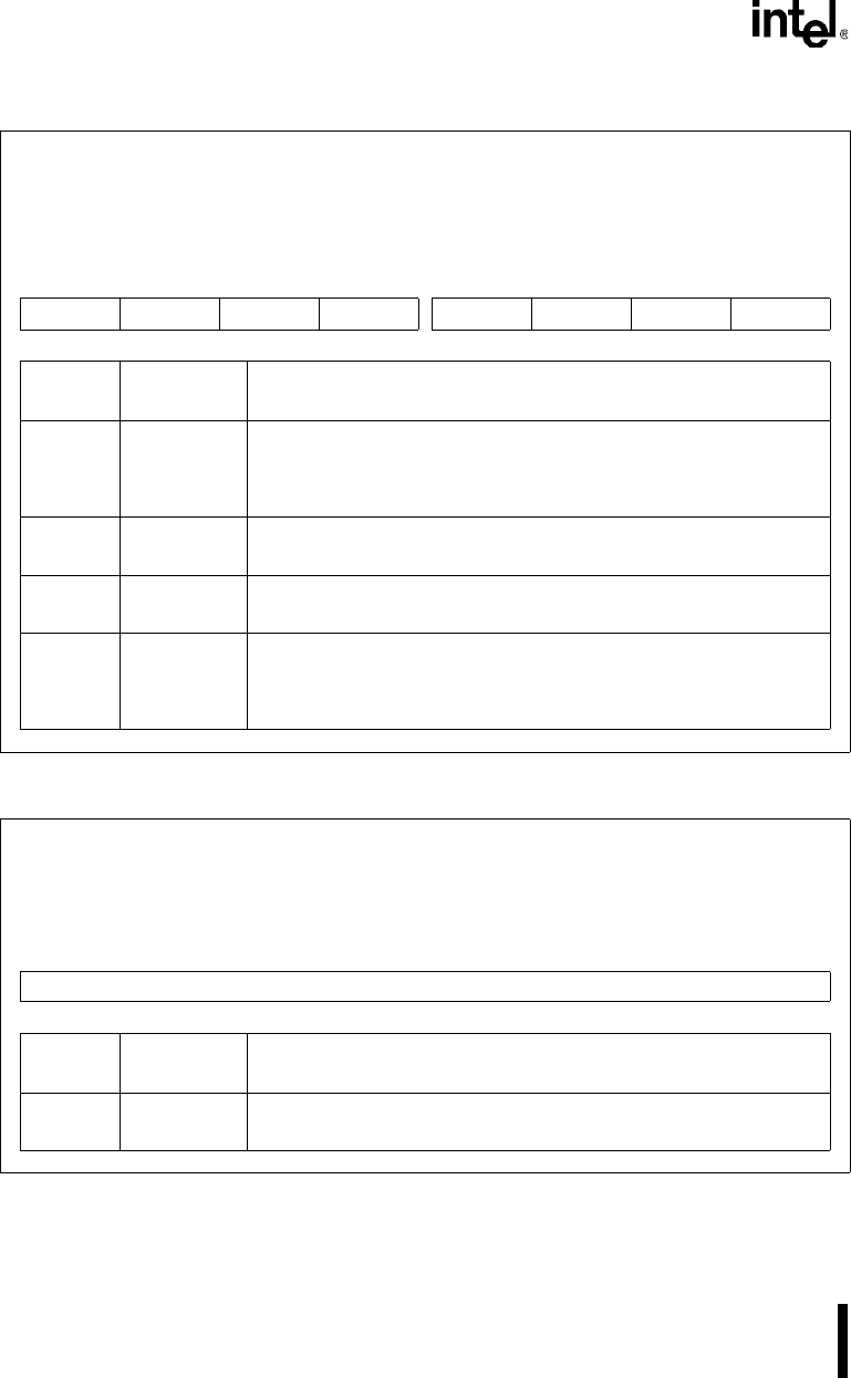
CCON
Address: S:D8H
Reset State: 00X0 0000B
PCA Timer/Counter Control Register. Contains the run control bit and overflow flag for the PCA
timer/counter, and the compare/capture flags for the five PCA compare/capture modules.
7 0
CF CR — CCF4 CCF3 CCF2 CCF1 CCF0
Bit
Number
Bit
Mnemonic
Function
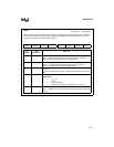
7 CF PCA Timer/Counter Overflow Flag:
Set by hardware when the PCA timer/counter rolls over. This generates
an interrupt request if the ECF interrupt enable bit in CMOD is set. CF
can be set by hardware or software but can be cleared only by software.
6 CR PCA Timer/Counter Run Control Bit:
Set and cleared by software to turn the PCA timer/counter on and off.
5 — Reserved:
The value read from this bit is indeterminate. Write a zero to this bit.
4:0 CCF4:0 PCA Module Compare/Capture Flags:
Set by hardware when a match or capture occurs. This generates a PCA
interrupt request if the ECCF
x
interrupt enable bit in the corresponding
CCAPM
x
register is set. Must be cleared by software.
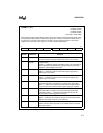
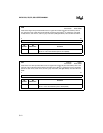
CH, CL
Address: S:F9H
S:E9H
Reset State: 0000 0000B
CH, CL Registers. These registers operate in cascade to form the 16-bit PCA timer/counter.
7 0
High/Low Byte PCA Timer/Counter
Bit
Number
Bit
Mnemonic
Function
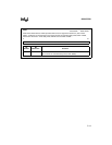
7:0 CH.7:0
CL.7:0
High byte of the PCA timer/counter
Low byte of the PCA timer/counter


