8XC251SA, SB, SP, SQ USER’S MANUAL
A-62
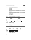
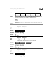
Flags:
Example: Register 0 contains 7EH (011111110B) and on-chip RAM locations 7EH and 7FH contain
0FFH and 40H, respectively. After executing the instruction sequence
INC @R0
INC R0
INC @R0
register 0 contains 7FH and on-chip RAM locations 7EH and 7FH contain 00H and 41H,
respectively.
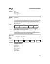
Variations
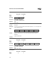
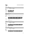
INC A
Binary Mode Source Mode
Bytes: 11
States: 11
Hex Code in: Binary Mode = [Encoding]
Source Mode = [Encoding]
Operation: INC
(A) ← (A) + 1
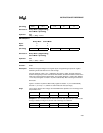
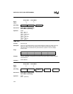
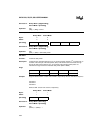
INC dir8
Binary Mode Source Mode
Bytes: 22
States: 2† 2†
†If this instruction addresses a port (P
x
,
x
= 0–3), add 2 states.
Hex Code in: Binary Mode = [Encoding]
Source Mode = [Encoding]
Operation: INC
(dir8) ← (dir8) + 1
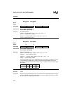
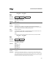
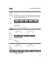
INC @Ri
Binary Mode Source Mode
Bytes: 12
States: 34
Hex Code in: Binary Mode = [Encoding]
Source Mode = [A5][Encoding]
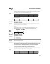
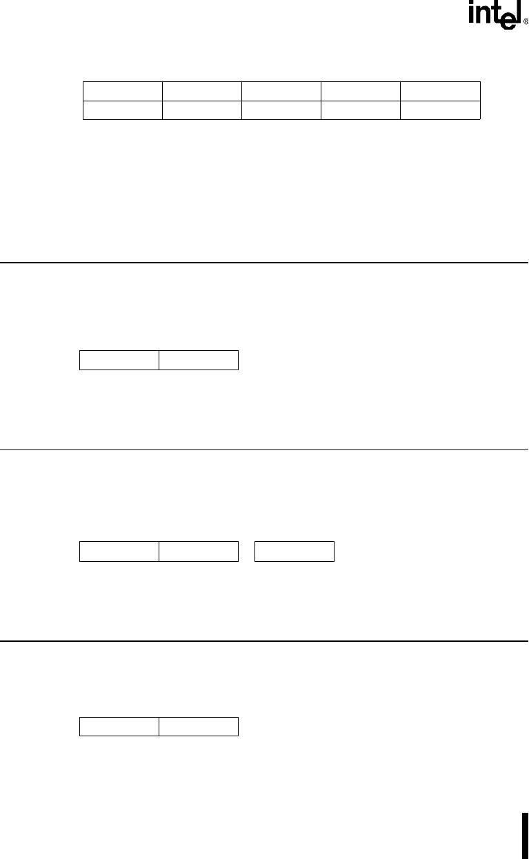
CY AC OV N Z
———✓✓
[Encoding] 0 0 0 0 0 1 0 0
[Encoding] 0 0 0 0 0 1 0 1 direct addr
[Encoding] 0 0 0 0 0 1 1 i


