4-13
DEVICE CONFIGURATION
4.5.3.3 Configuration Bit XALE#
Clearing XALE# (UCONFIG0.4) extends the time ALE is asserted from T
OSC
to 3T
OSC
. This ac-
commodates an address latch that is too slow for the normal ALE signal. Section 13.4.2, “Extend-
ing ALE,” shows an external bus cycle with ALE extended.
4.6 OPCODE CONFIGURATIONS (SRC)
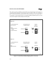
The SRC configuration bit (UCONFIG0.0) selects the source mode or binary mode opcode ar-
rangement. Opcodes for the MCS 251 architecture are listed in Table A-6 on page A-4 and Table
A-7 on page A-5. Note that in Table A-6 every opcode (00H–FFH), is used for an instruction ex-
cept A5H (ESC) which provides an alternative set of opcodes for columns 6H through FH. The
SRC bit selects which set of opcodes is assigned to columns 6H through FH and which set is the
alternative.
Binary mode and source mode refer to two ways of assigning opcodes to the instruction set for
the MCS 251 architecture. One of these modes must be selected when the chip is configured. De-
pending on the application, binary mode or source mode may produce more efficient code. This
section describes the binary and source modes and provides some guidelines for selecting the
mode for your application.
The MCS 251 architecture has two types of instructions:
• instructions that originate in the MCS 51 architecture
• instructions that are unique to the MCS 251 architecture
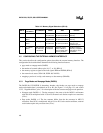
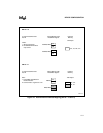
Table 4-3. RD#, WR#, PSEN# External Wait States
8XC251S
x
Regions
00: FE: FF:
WSA1# WSA0#
00
01
10
11
3 Wait States
2 Wait States
1 Wait State
0 Wait States
Region 01: WSB1# WSB0#
00
01
10
11
3 Wait States
2 Wait States
1 Wait State
0 Wait States


