


Companion 27
The diagnostics feature of your Golden
Companion’s “Rhino” microprocessor-
based motor control board functions as
follows:
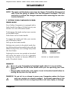
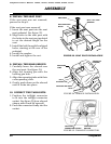
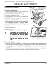
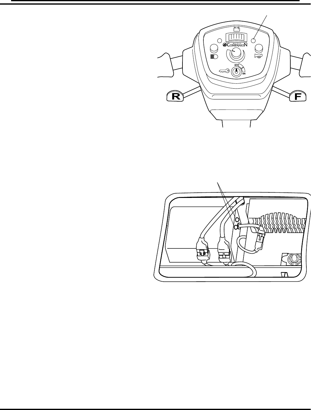
• Any fault condition on the “Rhino”
controller or on an associated system
will cause the Power-on/diagnostics
LED (see figure 43) to flash.
• The flashing of the LED occurs as one
flash or as a series of flashes separated
by a two-second pause.
• The number of flashes in each series
is referred to as the “Flash Code.”
• The flash code indicates the nature of
the condition or fault.
THE FLASH CODES
1 Flash
• Indicates that the battery voltage (with
the thumb levers in the neutral posi-
tion) is below 23.3 volts.
• The batteries need to be charged.
• Your Companion will continue to op-
erate until the voltage falls to 17.5
volts.
• As the voltage drops you will experi-
ence a power loss.
Remedy: Charge your Companion’s bat-
teries. See section XI. “Care
and Maintenance.”
DIAGNOSTICS
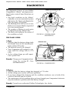
POWER-ON/DIAGNOSTICS LED
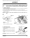
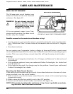
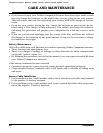
FIGURE 44. CHARGER LED’S
2 Flashes
• Indicates that the battery voltage has dropped to 17.5 volts.
• At this voltage your scooter will cease operation.
• If you have charged the batteries and the condition continues, one or both of the
scooter’s batteries may be at fault.
• The continuance of this condition after you have charged your Companion’s batteries
may also indicate a problem with the battery charger.
Remedy: Consult your authorized Golden Technologies, Inc. dealer.
FIGURE 43. CONTROL PANEL
DIAGNOSTICS
CHARGER LED’S
Companion Owner's Manual: GC222, GC223, GC322, GC323, GC325, GC421