


Companion 23
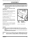
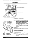
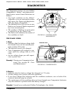
6. ELECTRICAL CONNECTIONS
NOTE: The electrical connectors on your Com-
panion have been designed so that only
the correct connector will fit in its ap-
propriate mating/plug receptacle.
When inserting a connector into its
mating plug receptacle, make certain
that the locking ears (see figure 18, page
18, for example of locking ears) “click”
into place.
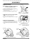
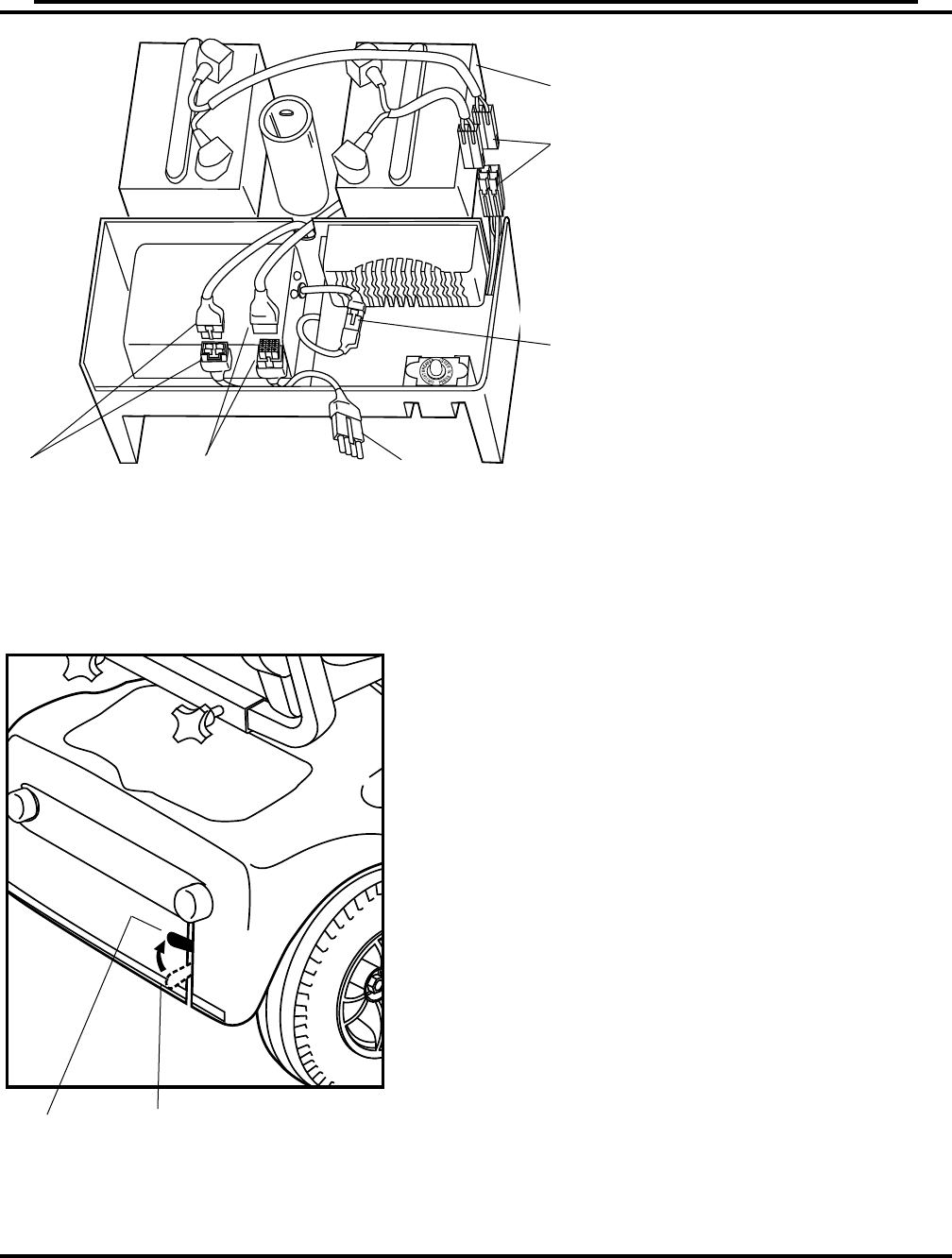
See figure 31.
Connect the motor/brake connector, if it has been
disconnected.
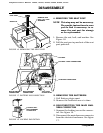
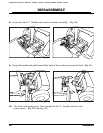
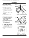
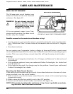
7. SET THE BRAKE HANDLE
1. Move the brake handle to the engaged “up”
position. See figure 32.
NOTE: Your Companion will only operate if the
brake handle is left in the engaged “up”
position.
ASSEMBLY
BATTERY
CHARGER CONNECTORS
MOTOR/BRAKE
CONNECTORS
MAIN HARNESS
CONNECTORS
BATTERY CABLE CONNECTORS
FIGURE 31. ELECTRICAL CONNECTIONS
TAIL LIGHT
CONNECTORS
BRAKE
HANDLE
ENGAGED
BRAKE HANDLE
DISENGAGED
(FREEWHEEL MODE)
FIGURE 32. BRAKE HANDLE
Companion Owner's Manual: GC222, GC223, GC322, GC323, GC325, GC421