


Electrical Safety Analyzer
Performing Electrical Safety Tests
39
To perform an alternative applied part leakage test:
1. Press B.
2. Press the soft key labeled More.
3. Select the desired applied part groupings using
G and H.
4. Press the soft key labeled Select.
5. Press the soft key labeled Alternative A.P..
6. Press T to apply the test voltage and read the
current in the display.
7. Press F or E to advance to the next applied part
group(s) of a single function if applicable. Pressing
T to read leakage current for each group.
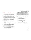
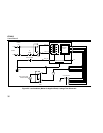
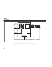
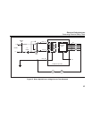
Figure 25 shows the electrical connections between the
Analyzer and the DUT during an Alternative Applied Part
Leakage current test.
Note
If there are more than five applied parts to
connect to the Analyzer, see Using the 1210
Adapter later in this manual.
Performing a Direct Equipment Leakage Test
Note
The Direct Equipment Leakage test is available
when the EN62353 standard is selected.
The Direct Equipment Leakage Current test measures the
leakage current between all applied parts and the exposed
conductive surface on the housing, to mains earth.
To perform a direct equipment test:
1. Press B.
The direct equipment test is the default test and should
already be selected.
2. Press T to apply the voltage and read the leakage
current in the display
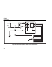
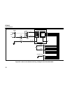
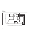
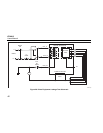
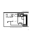
Figure 26 shows the electrical connections between the
Analyzer and the DUT during a Direct Equipment Leakage
Current Test.
The following outlet conditions apply when performing this
test:
• Normal Polarity, Closed Earth
• Normal Polarity, Open Earth
• Reversed Polarity, Closed Earth
• Reversed Polarity, Open Earth
Note
If there are more than five applied parts to
connect to the Analyzer, see Using the 1210
Adapter later in this manual.