


Electrical Safety Analyzer
Performing Electrical Safety Tests
33
Performing Lead-to-Lead (Patient Auxiliary) Leakage
Tests
Note
The Lead-to-Lead (Patient Auxiliary) leakage test
is available when the IEC60601 or ANSI/AAMI
ES1-1993 standard is selected.
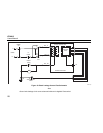
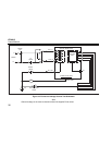
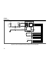
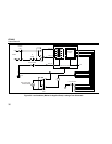
To measure the leakage current through each applied part
or lead and selected combination of lead connections (all
other or between two), press the softkey labeled Lead to
Lead from the Leakage Test main menu shown in
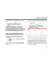
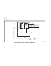
Figure 17. Figure 22 shows the electrical connections
between the Analyzer and the DUT during a Lead-to-Lead
(Patient Auxiliary) Leakage Current Test.
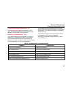
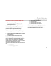
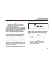
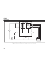
The Lead-to-Lead (Patient Auxiliary) Leakage test adds a
diagram of the applied parts connection posts to the
display, as shown in Figure 21. In the figure, the applied
parts post RA/R is shown above the other posts. This
indicates that the leakage measurement is being made
from RA/R to all others. To move to the next applied part
post, press F. The first post will appear inline with the
other posts while the LL/F post appears above all others.
This indicates the second leakage measurement is being
made from LL/F to all others. Continue pressing F or E to
move from one connection post to another and noting the
measured current in the display.
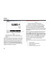
After each post is isolated individually, the Lead-to-Lead
(Patient Auxiliary) Leakage test measures current of three
different combinations of posts tied together: RA/R and
LL/F, RA/R and LA/L, or LL/F and LA/L.
fis107.eps
Figure 21. Applied Parts Connection Posts Display
Within the Lead-to-Lead (Patient Auxiliary) Leakage test, a
number of fault measurements can be made. Pressing
P switches the polarity of the mains voltage applied
to the Analyzer’s test receptacle between Normal, Off,
Reverse, and Off. Pressing N opens and closes the
neutral connection to the Analyzer’s test receptacle.
Pressing Dopens and closes the earth or ground
connection to the Analyzer’s test receptacle.
Note
If there are more than five applied parts to
connect to the Analyzer, see Using the 1210
Adapter later in this manual.