


vii
List of Figures
Figure Title Page
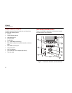
1. Front-Panel Controls and Connections ................................................................................. 4
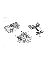
2. Side and Top-Panel Connections.......................................................................................... 6
3. Analyzer Ready for Operation ............................................................................................... 8
4. DUT Connections to the Analyzer ......................................................................................... 9
5. Leakage Current Menu.......................................................................................................... 10
6. Setup Menu........................................................................................................................... 11
7. Mains Voltage Test Menu...................................................................................................... 13
8. DUT Ground Resistance Measurement................................................................................. 14
9. Ground Wire (Protective Earth) Resistance Measurement Connections............................... 16
10. Ground Wire (Protective Earth) Resistance Measurement Schematic .................................. 18
11. Insulation Resistance Measurement ..................................................................................... 19
12. Mains to Protective-Earth Insulation Resistance Test Schematic.......................................... 20
13. Applied Parts to Protective-Earth Insulation Test Schematic................................................. 21
14. Mains to Applied Parts Insulation Test Schematic................................................................. 22
15. Mains to Non-Earth Accessible Conductive Points Schematic .............................................. 23