


ESA612
Users Manual
14
Prior to conducting any leakage tests with the Analyzer, it
is best to test the integrity of the ground connection
between the Analyzer’s test receptacle ground and the
DUT’s Protective earth ground or enclosure with this test.
To access the Ground Wire (Protective Earth) ∅/Null
Resistance Test menu press O.
Note
The DUT is powered off for this test.
To perform a ground wire resistance test:
1. Ensure the power cord from the DUT is plugged into
the Analyzer’s test receptacle.
2. Press O to reveal the resistance function menu.
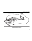
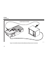
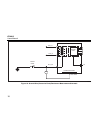
3. Connect one end of a test lead to the V/Ω/A jack as
shown in Figure 9.
4. If using an accessories probe, connect it to the other
end of the test lead and place the probe tip into the
∅/Null jack. If using an alligator clip accessory,
connect it to the other end of the test lead, place the
null post adapter in the ∅/Null jack, and clamp the
alligator clip to the null post adapter.
5. Connect the other end of the test lead to ∅/Null jack.
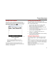
6. Press the softkey labeled Zero Leads. The Analyzer
zeroes out the measurement to cancel the test lead
resistance.
7. Connect the test lead coming from the ∅/Null jack to
the DUT enclosure or protective earth connection.
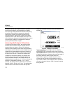
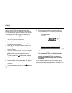
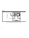
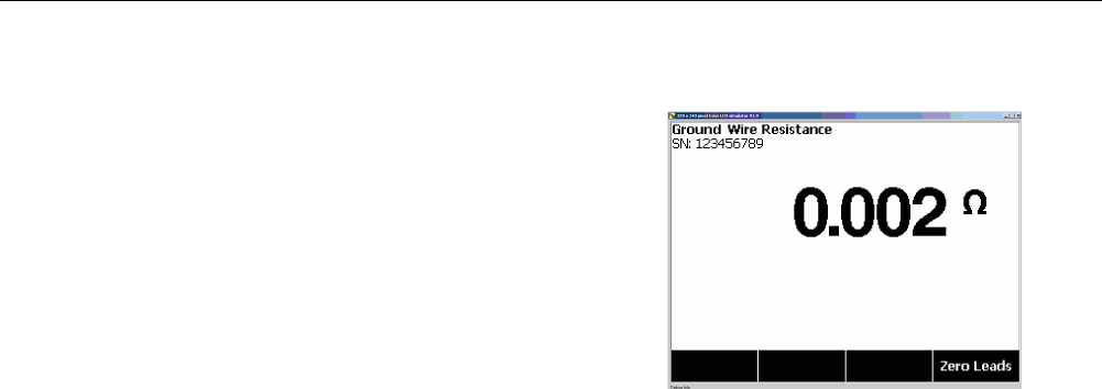
8. The measured resistance is displayed as shown in
Figure 8 after the DUT connection(s) is/are made.
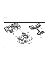
fis105.jpg
Figure 8. DUT Ground Resistance Measurement
WX Warning
To avoid electric shock, remove the null post
adapter from the ∅/Null jack after a test lead
zero is performed. The ∅/Null jack becomes
potentially hazardous during some of the test
conditions.
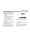
A low resistance reading is required to confirm a good
ground connection through the power cord. Refer to the
appropriate electrical safety standard for the specific limit
value to be followed.