


Instruction Manual
748213-S
April 2002
Rosemount Analytical Inc. A Division of Emerson Process Management Maintenance and Service 6-5
Model 755R
a. Source Lamp
The simplest check of the source lamp is
to verify that it is lit. Another check is
done by removing the housing cover and
viewing the lamp through the photocell
alignment hole (see Figure 6-3, page 6-4).
If the photocell is not illuminated, test the
voltage across TP2 to TP5 (ground). This
voltage should be 2.2 V ±0.2 VDC. If
reading is correct, the lamp may be
burned out; also inspect the cable for
continuity. If voltage reading is not 2.2 V
±0.2 VDC, the Power Supply Board must
be replaced.
b. Photocell
If the photocells are on, observe through
the photocell alignment hole. The image
should be steady. Disconnect the line
power and observe the image when you
reconnect the power. It should come up
from the side and seek a position that
equally illuminates the photocells.
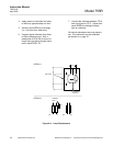
c. Suspension
Turn electrical power to instrument OFF.
Remove optical bench assembly (see
Figure 6-1A, page 6-3). With 100% nitro-
gen flowing through the analyzer, note
position of the suspension. Then admit
air and note response of the suspension.
It should rotate clockwise as viewed from
the top, and to the right as viewed though
the window. Failure to rotate indicates
that the suspension has been damaged
and detector assembly must be replaced.
See Section 6-5c, page 6-7.
If the suspension has been changed, the
cause may be improper operating condi-
tions.
6-5 REPLACEMENT OF DETECTOR/MAGNET
COMPONENTS
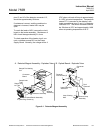
a. Source Lamp
Removal/Installation
The source lamp is held in the optical
bench assembly by a set screw (see Fig-
ure 6-1B, page 6-3). The two lamp leads
are connected to J12.
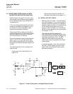
The red line on the lamp base must align
with the set screw (see Figure 6-4A). The
base of the lamp should extend from the
hole approximately 1/4 inch. Tighten set
screw when lamp is aligned.
Realign the photocell per Section 6-5b,
page 6-5.
b. Photocell
Removal/Installation
Refer to Figure 6-1B, page 6-3. Note lo-
cation of photocell leads in connector J12.
Remove leads. Remove photocell lock
screws (2), slide photocell out.
Reverse the removal procedure for in-
stallation. Align photocell (see below).
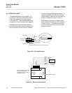
Alignment
The adjustments in this procedure are
made on the Control Board. With zero
gas flowing:
1. Place a digital voltmeter between the
wiper of zero potentiometer (R13) and
TP7 (ground). Adjust for 0 VDC.
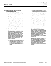
2. Remove the voltmeter from R13 and
place on R10 (see Figure 6-4B, page
6-6). Adjust R9 for 0 VDC.
3. Remove the voltmeter from R10 and
place on TP8. Move the photocell to
obtain a DC voltage as close to 0 mV
as possible, but no more than ±750
mV.