


Instruction Manual
748213-S
April 2002
4-4 Theory Rosemount Analytical Inc. A Division of Emerson Process Management
Model 755R
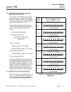
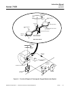
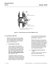
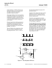
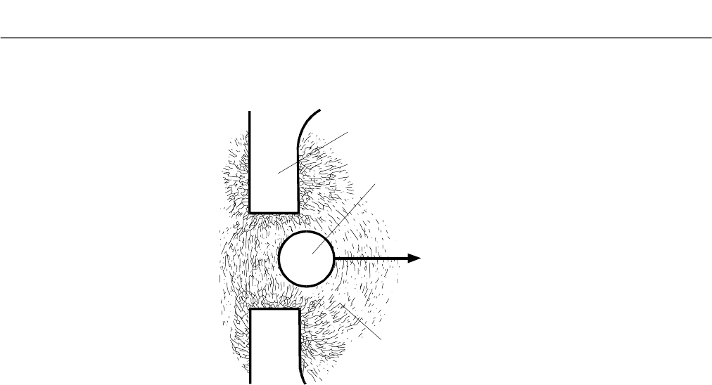
Figure 4-2. Spherical Body in Non-Uniform Magnetic Field
4-3 ELECTRONIC CIRCUITRY
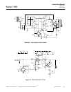
Electronic circuitry is shown in the Control
Board schematic diagram, Drawing 652826,
and is described briefly in the following sec-
tions. For detailed circuit analysis, refer to
Section 5 Circuit Analysis.
a. Detector/Magnet Assembly
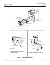
A cross-sectional view of the optical
bench and detector assemblies is shown
in Figure 4-3B, page 4-7. Source lamp
DS1, powered by a supply section within
the Power Supply Board assembly (See
Section 4-3c, page 4-5) directs a light
beam onto the mirror attached to the test
body. The mirror reflects the beam onto
dual photocell BT1, BT2.
The difference between the signals de-
veloped by the two halves of the photocell
constitutes the error signal supplied to the
input of amplifier U1 on the Control Board
assembly. Amplifier U1 drives U2 which,
in turn, supplies the restoring current to
the titanium wire loop on the test body
(See Section 4-1, page 4-1).
Detector temperature is sensed by ther-
mistor RT1, an integral part of the detec-
tor assembly (See Figure 4-3B, page 4-7).
The thermistor provides the input signal to
the detector temperature control section
of the Power Supply Board assembly:
HR1, mounted on the top of the magnet,
and HR2, mounted permanently on the
rear of the detector assembly.
b. Control Board and Associated Cir-
cuitry
The Control Board consists of signal con-
ditioning and control circuitry.
This circuitry includes the following:
Shaded
Pole
Piece
Sphere
(Magnetic Susceptibility = k
o
)
F
k
Sample Gas
(Magnetic Susceptibility = k
)
Note:
As percentage of oxygen in sample gas increases,
displacement force (F
k
) increases.