


Instruction Manual
748213-S
April 2002
2-6 Installation Rosemount Analytical Inc. A Division of Emerson Process Management
Model 755R
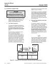
2-5 ELECTRICAL CONNECTIONS
WARNING
ELECTRICAL SHOCK HAZARD
For safety and proper performance, this
instrument must be connected to a prop-
erly grounded three-wire source of supply.
Cable connections for AC power, recorder
output, and alarm output are shown in In-
stallation Drawing, 654015, and are ex-
plained in the following sections.
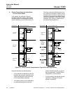
a. Line Power Connection
The analyzer is supplied, as ordered, for
operation on 115 VAC or 230 VAC, 50/60
Hz. Ensure that the power source con-
forms to the requirements of the individual
instrument, as noted on the name-rating
plate.
Electrical power is supplied to the ana-
lyzer via a customer-supplied
three-conductor cable, type SJT, mini-
mum wire size 18 AWG. Route power ca-
ble through conduit and into appropriate
opening in the instrument case. Connect
power leads to HOT, NEUT, and GND
terminals on the I/O board. Connect ana-
lyzer to power source via an external fuse
or breaker, in accordance with local
codes. Do not draw power for associated
equipment from the analyzer power cable
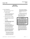
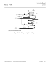
(Refer to Figure 2-3 below).
If the analyzer is mounted in a protected
rack or cabinet or on a bench, an acces-
sory kit (P/N 654008) is available which
provides a 10-foot North American power
cord set and a liquid-tight feed through
gland for the power cable hole. The kit
also contains four enclosure support feet
for bench top use.
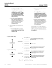
b. Recorder Output Selection and Cable
Connections
If a recorder, controller, or other output
device is used, connect it to the analyzer
via a number 22 or number 24 AWG
two-conductor shielded cable. Route the
cable into the case through the liquid-tight
feed through gland in the Recorder Out-
put opening (See Installation Drawing,
654015). Connect the shield only at the
recorder end or the analyzer end, not to
both at the same time because a ground
loop may occur.
NOTE:
Route recorder cable through a separate
cable gland (P/N 899329) or conduit not
with power cable or alarm output cable.
Cable connections and output selection
for potentiometric and current-actuated
devices are explained below.
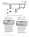
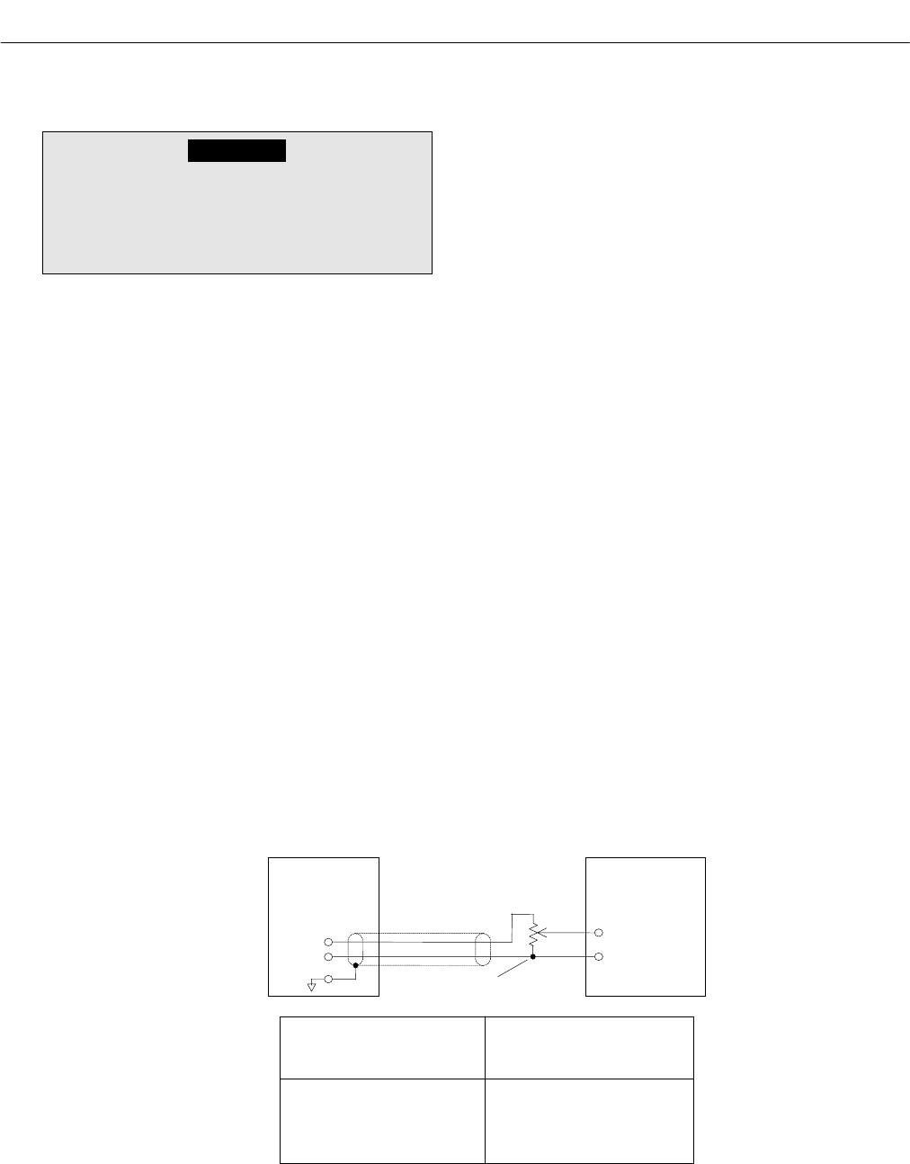
Figure 2-3. Connections for Potentiometric Recorder with Non-Standard Span
755R
Analyzer
Potentiometric
Recorder
I
npu
t
Terminals
(V
er
if
y po
l
ar
it
y
is correct)Voltage Divider
(Customer Supplied)
Position of Recorder Output
Selector Plug
Minimum Permissible
Resistance for R1 + R2
(ohms)
10 mV 1K
100 mV 10K
1 V 100K
5 V 2K