


Instruction Manual
748213-S
April 2002
2-12 Installation Rosemount Analytical Inc. A Division of Emerson Process Management
Model 755R
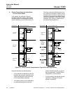
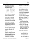
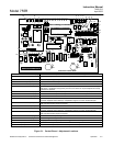
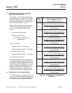
2-6 REMOTE RANGE CHANGE OPTION
The power supply circuitry on the Remote
Range Board 646004 must be jumpered for
the correct line voltage, either 115 VAC or 230
VAC. See Drawings # 656081 (Table 2) and
646090 for correct jumper locations.
On the Remote Range Board, an additional
option exists: for using either the on-board 12
V to drive the range select relays or an exter-
nal 12 V supply.
To use an external supply:
1. Remove the E to F jumper (DWG 646090).
2. Apply the external 12 V to J3-5.
3. Program the remote controller to pull the
range bits, J3-1 through J3-4, low. (See
Table 2-1 below.)
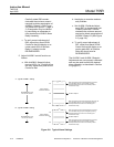
To use the internal 12 V supply:
1. Verify the E to F jumper is in place.
2. Connect the controller's common to J3-6
to reference the instrument's common to
the controller's common.
NOTE
DO NOT connect anything to J3-5.
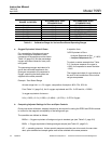
3. Connect J3-1 to J3-4, as shown in the
truth table below, to switch ranges.
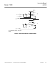
Remember that you are dealing with inverse
logic and not normal binary addresses. Also,
this process switches the recorder output
only, and does not affect the front panel dis-
play.
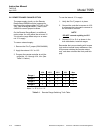
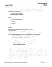
J3-4 J3-3 J3-2 J3-1 Hex
Range 1
1 1 1 0 E
Range 2
1 1 0 1 D
Range 3
1 0 1 1 B
Range 4
0 1 1 1 7
Note: 1 = 12 V, 0 << 1 V.
Table 2-1. Remote Range Switching Truth Table