


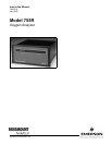

Instruction Manual
748213-S
April 2002
ii Contents Rosemount Analytical Inc. A Division of Emerson Process Management
Model 755R
3-0 OPERATION .........................................................................................................................3-1
3-1 Overview................................................................................................................................3-1
3-2 Operating Range Selection ...................................................................................................3-1
3-3 Startup Procedure .................................................................................................................3-1
3-4 Calibration..............................................................................................................................3-1
a. Calibration with Zero and Span Standard Gases ...........................................................3-1
3-5 Compensation For Composition Of Background Gas...........................................................3-2
a. Oxygen Equivalent Value of Gases ................................................................................3-4
b. Computing Adjusted Settings for Zero and Span Controls.............................................3-4
3-6 Selection Of Setpoints And Deadband On Alarm Option......................................................3-7
3-7 Current Output Board (Option) ..............................................................................................3-7
3-8 Routine Operation .................................................................................................................3-8
3-9 Effect of Barometric Pressure Changes on Instrument Readout ..........................................3-8
3-10 Calibration Frequency ...........................................................................................................3-8
4-0 THEORY................................................................................................................................4-1
4-1 Principles of Operation ..........................................................................................................4-1
4-2 Variables Influencing Paramagnetic Oxygen Measurements ...............................................4-2
a. Pressure Effects..............................................................................................................4-2
4-3 Electronic Circuitry.................................................................................................................4-4
a. Detector/Magnet Assembly.............................................................................................4-4
b. Control Board and Associated Circuitry..........................................................................4-4
c. Power Supply Board Assembly.......................................................................................4-5
d. Isolated Current Output Board (Optional) .......................................................................4-6
5-0 CIRCUIT ANALYSIS.............................................................................................................5-1
5-1 Circuit Operation....................................................................................................................5-1
5-2 ±15 VDC Power Supply.........................................................................................................5-1
5-3 Case Heater Control Circuit...................................................................................................5-1
5-4 Detector Heater Control Circuit .............................................................................................5-6
5-5 Detector Light Source Control Circuit....................................................................................5-7
5-6 Detector with First Stage Amplifier ........................................................................................5-8
5-7 Buffer Amplifiers U8 and U10 with Associated Anticipation Function ...................................5-10
5-8 Digital Output Circuit..............................................................................................................5-10
5-9 Analog Output Circuits for Recorder and Alarms ..................................................................5-11
a. First Stage Amplifier........................................................................................................5-11
b. Second Stage Amplifier ..................................................................................................5-11
6-0 MAINTENANCE AND SERVICE ..........................................................................................6-1
6-1 Initial Checkout With Standard Gases...................................................................................6-1
a. Control Board Checkout..................................................................................................6-1
6-2 Heating Circuits .....................................................................................................................6-2
a. Case Heater Control Circuit............................................................................................6-2
6-3 Detector/Magnet Heating Circuit ...........................................................................................6-2
6-4 Detector Check......................................................................................................................6-4
a. Source Lamp...................................................................................................................6-5
b. Photocell .........................................................................................................................6-5
c. Suspension .....................................................................................................................6-5