


Instruction Manual
748213-S
April 2002
5-2 Circuit Analysis Rosemount Analytical Inc. A Division of Emerson Process Management
Model 755R
+15V
+15V
INPUT
1
2
+
R69
2M
-
R70
20M
C38
0.18uF
-15V
+15V
R72
4.75K
-
+
R73
20M
-15V
R68
3.3K
R71
21.5K
-1.88 VDC
Source
OUTPUT
159mV
0
°
180
°
360
°
0
°
180
°
100µ
-15V
-1.7V
ON ONOFF
OFF OFFON
COMP 1
COMP 2
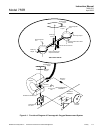
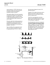
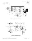
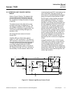
output remains at -15 VDC until the incom-
ing signal crosses zero value and the posi-
tive signal causes the comparator 2
transistor to cease to conduct.
Summing the effects of the two comparators
in the OR circuit results in no output from the
comparators for about 4° of the sine wave,
2° after the signal goes positive (0 to 2°) and
2° before the positive signal reaches 180°
(178° to 180°).
During the period that neither comparator is
conducting, the value on the OR bus is the
potential from the temperature-sensing
bridge plus the effect of the ramp generator,
probably -1.88 ±0.03 V.
The on-off effect of the comparators to the
OR circuit results in application of a posi-
tive-going pulse (from -15 V to -1.89 V) to
the temperature bridge at the rate of 120
pulses per second.
Capacitor C36 is added to the input circuit to
delay the incoming AC signal so that the
pulses will occur at or just after the line fre-
quency crossover point.
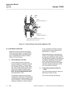
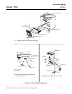
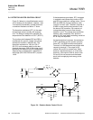
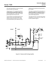
Circuits for a ramp generator and a tem-
perature-sensing bridge are part of the case
heater control circuit (See Figure 5-2, page
5-3 and Figure 5-3, page 5-3).
On initial application of power to comparator
of Figure 5-2 (page 5-3), no potential exists
on the inverting terminal because no charge
exists on capacitor, C37. If the transistor of
comparator 3 does not conduct, +15V is at
the output terminal. With +15V at the output,
the potential on the non-inverting terminals
will be about ±2.3 V because of the resis-
tance divider, R75, R76.
Figure 5-1. Two-Comparator OR Circuit