


Instruction Manual
748213-S
April 2002
4-6 Theory Rosemount Analytical Inc. A Division of Emerson Process Management
Model 755R
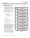
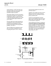
±15 V Power Supply Section
This section provides DC voltage required
for various amplifiers and other circuits.
Fullwave rectifier bridge CR5 provides
both positive and negative outputs. Each
is routed through an associated series
type integrated circuit, voltage regulator,
providing regulated outputs of +15 V and
-15 V.
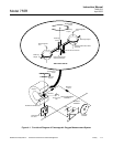
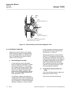
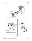
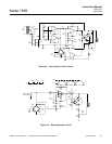
Detector Temperature Control Section
This section maintains the detector at a
controlled temperature of 150°F (66°C).
Temperature is sensed by RT1, a resis-
tance element permanently attached to
the detector assembly. The signal from
the sensor is applied to amplifier AR6,
which drives transistors Q2 and Q3, thus
controlling application of DC power from
full wave rectifier bridge CR6 to two heat-
ers within the detector/magnet assembly:
HR1, mounted on the top of the magnet
and HR2, permanently mounted on the
rear of the detector assembly.
Detector Compartment Temperature
Control Section
This section maintains the interior of the
detector compartment at a controlled
temperature of 140°F (60°C). Tempera-
ture is sensed by a thermistor located in
the detector compartment and plugged
into the Control Board assembly.
The circuit provides an on-off control of
heater element HR3 via TRIAC element
Q7. Heater HR3 is a part of the heater/fan
assembly.
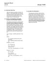
a. Isolated Current Output Board (Op-
tional)
An isolated current output is obtainable by
insertion of an optional plug-in circuit
board into receptacle J1 on the Control
Board (see Figure 3-1, page 3-3). The
current outputs available by this board are
0 to 20 mA or 4 to 20 mA.