


Instruction Manual
748213-S
April 2002
2-8 Installation Rosemount Analytical Inc. A Division of Emerson Process Management
Model 755R
NO
COM
NC
NO
COM
NC
RESET
RESET
No. 1
No. 2
Alarm Bell
or Lamp
N
H
115 VAC
NO
COM
NC
NO
COM
NC
RESET
RESET
No. 1
No. 2
Alarm Bell
or Lamp
N
H
115 VAC
NO
COM
NC
NO
COM
NC
RESET
RESET
No. 1
No. 2
NO
COM
NC
NO
COM
NC
RESET
RESET
No. 1
No. 2
Alarm Bell
or Lamp
N
H
115 VAC
NO
COM
NC
NO
COM
NC
RESET
RESET
No. 1
No. 2
Alarm Bell
or Lamp
N
H
115 VAC
NO
COM
NC
NO
COM
NC
RESET
RESET
No. 1
No. 2
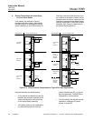
REQUIREMENT TYPICAL CONNECTIONSREQUIREMENT TYPICAL CONNECTIONS
Low Alarm,
Fail-Safe
Low Control
Limit,
Fail-Safe
Solenoid
Valve
N
H
115 VAC
High Alarm,
Fail-Safe
Low Control
Limit,
Fail-Safe
Solenoid
Valve
N
H
115 VAC
Solenoid
Valve
N
H
115 VAC
Lower
Low Alarm
Indicator,
Fail-Safe
Low Control,
Fail-Safe
Higher
High Alarm
Indicator,
Fail-Safe
High Control,
Fail-Safe
Solenoid
Valve
N
H
115 VAC
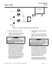
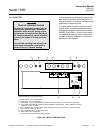
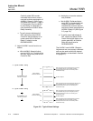
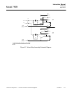
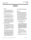
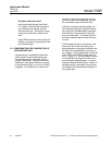
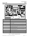
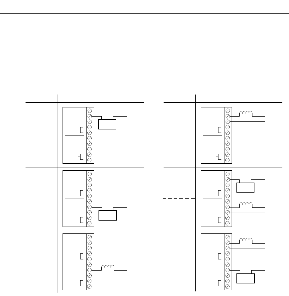
e. Output Connections and Initial Setup
for Dual Alarm Option
If so ordered, the analyzer is factory
equipped with alarm output. Alternatively,
the alarm feature is obtainable by subse-
quent installation of the 654019 Alarm Kit.
The alarm output provides two sets of re-
lay contacts for actuation of alarm and/or
process-control functions. Leads from the
customer-supplied external alarm system
connect to terminals on the 654019 Alarm
Assembly (See Figure 2-5 below and In-
terconnect Drawing 654014).
Figure 2-5. Relay Terminal Connections for Typical Fail-Safe Applications
Note the following recommendations:
•
A fuse should be inserted into the line
between the customer-supplied power
supply and the alarm relay terminals
on the Alarm Relay Assembly.
•
If the alarm contacts are connected to
any device that produces radio fre-
quency interference (RFI), it should
be arc suppressed. The 858728 Arc
Suppressor is recommended.
•
If at all possible, the analyzer should
operate on a different AC power
source, to avoid RFI.