


Instruction Manual
748213-S
April 2002
6-2 Maintenance and Service Rosemount Analytical Inc. A Division of Emerson Process Management
Model 755R
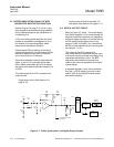
2. Adjust R29 clockwise and counter-
clockwise. The display should follow
accordingly and remain steady within
the adjustment limits of R29. If this
condition is met, refer to Section 6-6a
(page 6-7) for Control Board setup.
Before replacing the Control Board,
test for -15V at the junction of C1/J4-
7. Use the junction of CR1/R2 for
+15V, or any source of ±15V on the
board for the respective voltages.
3. If adjustment of R29 is not possible,
replace the Control Board.
Alarms
Set RANGE Select to lowest range or use
zero and span gases.
Current Output
Set RANGE Select to lowest range or use
zero and span gases.
When checkout complete, re-install De-
tector Isolation Plug. Configure Control
Board to original setup.
If the Control Board functions correctly,
the problem is either located in the De-
tector/Magnet Assembly or related to
temperature control.
6-2 HEATING CIRCUITS
To ensure against damage from overheating
in the event of malfunction, the heating cir-
cuits receive power via thermal fuses F2 and
F3. If temperature of a heated area exceeds
the permissible maximum, the associated fuse
melts, opening the circuit.
NOTE:
The thermal fuses should be plugged in,
NOT SOLDERED, as the fuse element
might melt and open the circuit.
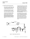
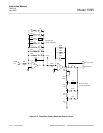
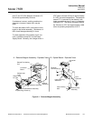
a. Case Heater Control Circuit
The case heater control circuit receives
power via thermal fuse F2 (setpoint
75°C). This fuse, accessible on the
Power Supply Board, may be checked for
continuity.
Detector compartment heater element
HR3, mounted on the heater/fan assem-
bly, has a normal resistance of 20 ohms.
To verify heater operation, carefully place
a hand on top of detector compartment.
Heat should be felt. If not, check the case
heating circuit.
Temperature sensor RT1 has a cold re-
sistance of 22.7K ohms and a normal op-
erating resistance of 20.2K ohms,
indicating normal operating temperature.
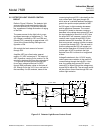
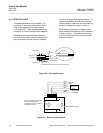
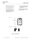
As a further check, disconnect plug P6 on
the Control Board, thus disconnecting
temperature sensor RT1. Substitute a
decade resistor box to simulate the re-
sistance of RT1. Also, connect an AC
voltmeter from the hot side of the line to
the neutral side of F2, located inside the
detector compartment.
Set the decade box for 20.2K ohms to
simulate RT1 at controlling temperature.
The voltmeter should show pulses of 1
VAC.
CAUTION
OVERHEATING
Avoid prolonged operation with the dec-
ade box set at 22.2K ohms, overheating
may result.
Set the decade box for 22.2K ohms to
simulate RT1 resistance at ambient tem-
perature. The voltmeter should show
pulses of 120 VAC.
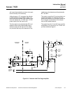
6-3 DETECTOR/MAGNET HEATING CIRCUIT
Heater HR1 is attached to the magnet.
Heater HR2 is attached to the rear of the de-
tector. Combined resistance of these two
parallel-connected heaters, as measured at