


3M Dynapro ET 350 Monitor User’s Installation Guide
60
6. Remove the bracket, find the DIP-Switch on the board, and move the
switch to the on position.
7. Replace the bracket and screws and close the enclosure.
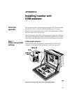
Step 2:
Make connections
To connect communications cables, follow these steps:
1. If the monitor has a hatch, the hatch must be open to access
connectors. Remove the four #6-32 Phillips screws affixing the hatch
to the monitor and open the hatch cover. For an illustration of the
locations of these screws, refer to Figure 13 on page 38.
2. Make sure that the monitor and host computer are powered off.
3. Connect one end of the combination keyboard, video, and mouse
cable to the local unit of the KVM extender and the multiple
connectors on the other end of the cable to the corresponding
connectors on the host computer.
4. Connect the serial cable between the KVM local unit and the host
computer.
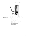
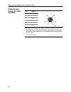
5. Interconnect the remote unit (in the ET 350 monitor enclosure) and
the local unit of the KVM extender using industry-standard structured
cabling (Category 5 UTP or STP, 4-pair) terminated with RJ-45 male
connectors. The appropriate connectors on the remote and local units
are labelled CAT5 (Figure 23). For information on pinning/pairing the
interconnecting cable, refer to Appendix C.
Important
To help ensure optimal performance and to reduce the effect of interference,
route the CAT5 cable away from generators, motors, compressors, fluorescent
lights, and other cables.