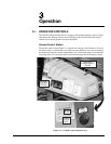
3 — OPERATION
3-3
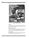
Outriggers Run Pushbutton
ed,
aulic valves to extend and retract the out-
perator lever retracts the cylinder to raise the outrigger.
r lever lowers the related outrigger. When released, the op-
s
and the boom rotation drive motor. Pulling a boom operator lever
rotation operator lever turns the boom clockwise. Pushing the operator
lever turns the boom counterclockwise. How far the lever is pushed or pulled controls the
al
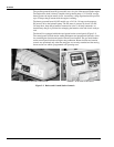
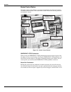
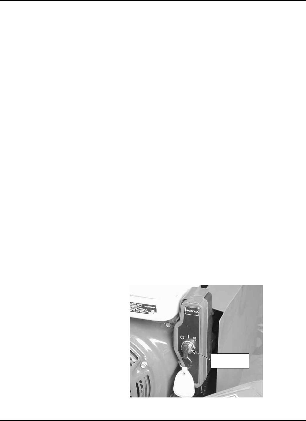
Engine Keyswitch (Gas M
On the gas model start and stop
the gasoline engine from ust be in the ON position
(as shown) to enable engine start-up from the work basket control station.
Holding the black outriggers run pushbutton in enables operation of the outrigger cylin-
ders. The outrigger cylinders can only be operated when the lift boom cylinders are re-
tracted.
Boom Run Pushbutton
Holding the green boom run pushbutton in enables operation of the lift boom cylinders.
The lift boom cylinders can only be operated when the outrigger cylinders are extend
the boom weight is removed from the trailer axle, and the trailer is level.
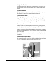
Outrigger Operator Levers
Four outrigger operator levers position the hydr
rigger cylinders. Lifting an o
Pushing down on an operato
erator levers return to the center (valve-off) position. Starting on your left, the outrigger
are numbered 1 through 4. A decal located below the outrigger valve manifold indicates
which operator lever controls which outrigger.
Boom Operator Levers
Four boom operator levers position proportional hydraulic valves to extend and retract
the boom lift cylinders
extends the cylinder to raise the boom. Pushing a boom operator lever lowers the related
boom. How far the lever is pushed or pulled controls the boom lift speed.
Pulling the boom
boom rotation speed.
When released, the boom operator levers return to the center (valve-off) position. A dec
located in front of the valve manifold shows which boom motion is controlled by each
operator lever.
odel only)
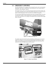
boom lift, the engine keyswitch (Figure 3-3) is used to
the ground position. The keyswitch m
ENGINE
KEYSWITCH
Figure 3-3. Engine Keyswitch


