Reference
3–24
WFM 601A, WFM 601E & WFM 601M User Manual
The Eye display bandwidth of the waveform monitor is 450 MHz, so it can not
display aberrations faster than this. Most receiver circuits are also bandwidth
limited and usually ignore fast transients. This common bandwidth makes the
waveform monitor a good indicator of problem sources in systems.
Measuring Rise Time. Rise time measurements provide a check on the perfor-
mance of sources and signal degradation by cabling.
To measure rise time, perform the following steps:
1. Perform the initial settings for Eye measurements described on page 3–22.
2. Select Variable Gain and size the waveform to 10 major divisions.
3. Use the Vert Pos bezel knob to position the bottom of the trace at the –.3 line
and check that the top is aligned with the .7 V line.
4. Enable the Timing Cursors.
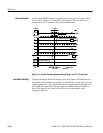
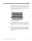
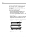
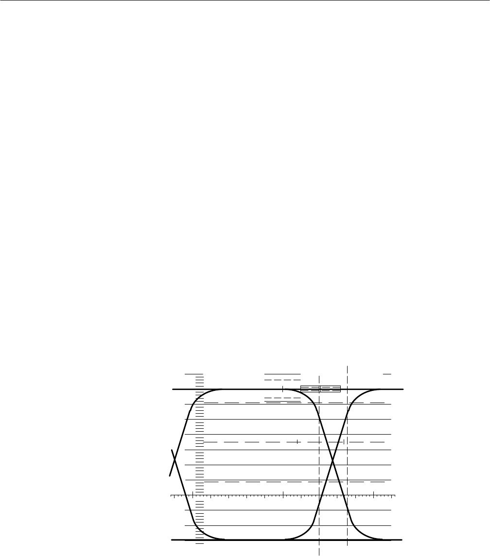
5. Align the cursors as shown in Figure 3–21. The first cursor is at the crossing
of the rising edge and –.1 V line. The second cursor is at the crossing of the
rising edge and the .5 V line. Use the horizontal MAG for greater accuracy
when adjusting the cursors.
6. The indicated nt time value is the standard 20 – 80% rise time measurement.
.7
.6
.8
.5
.4
.3
.2
.1
–.1
–.2
–.3
100%
50%
>100mV/DIV
OVERLAY
0.5nS/DIV
1 kHz
nT
.8nS
Figure 3–21: Timing Cursors alignment for measuring 20–80% rise time


