Reference
3–58
WFM 601A, WFM 601E & WFM 601M User Manual
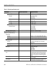
Video In
The VIDEO IN selections enable Serial input A or B and determine which
component signals are displayed. The SERIAL A and B button corresponds to
the SER A and B loop-through inputs on the rear panel. Only one input can be
active at a time.
The CH 1 button displays the Y or luminance signal. The CH 2 button displays
the Pb or B-Y chrominance signal. The CH 3 button displays the Pr or R-Y
chrominance signal. In the WFM AS RGB mode, CH 1 displays R, CH 2
displays G, and CH 3 displays B.
Waveform Display
The Waveform display mode displays voltage versus time for the selected video
input (A or B). You can display the three input video channels singly or in
combination. When you display more than one channel of the input signal, the
channel traces are overlaid.
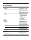
The waveform monitor uses a line-store memory in 1H and Sample Line Select
modes which allow it to display all video channels from the same video line. This
feature lets you view and measure concurrent data for all three channels.
The Line Select menu offers two or three modes depending on your model:
H 1H. Shows one line of a field or frame. A horizontal line on the output
monitor signal marks the selected line.
H 15H. Displays 15 successive lines.
H Sample (WFM 601M only). Picks a particular sample in a horizontal line and
indicates it with a visible marker on the line.
Cursors are available to measure time and amplitude differences.
Horizontal and vertical magnification are available by pressing the MAG and
GAIN buttons. Magnification is also valid during cursor measurements.
Line Select
Cursors
Gain


