


14
Installation
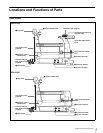
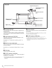
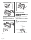
t SCREEN SIZE MARKER switch
Used to control the display of the screen size marker as
follows:
ON ( ): Areas outside the specified ratio area will be
darkened.
ON ( ): The screen size marker (white lines) will be
displayed.
OFF: The screen size marker will not be displayed.
u MARKER switch
Used to control the display of the marker as follows:
ON: A marker selected from the menu will be displayed on
the viewfinder screen.
OFF: The marker will not be displayed.
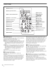
v UP TALLY switch [1500][1505]
Set whether or not the camera’s Up Tally lamp and the
lens’ tally lamp will light when the camera receives a red
tally signal.
ON: The tally lamps will light.
OFF: The tally lamps will not light.
w DISPLAY switch
The functions of the DISPLAY switch are as follows:
ON: Text and messages describing the camera settings and
operating status may be displayed on the viewfinder
screen.
OFF: Status messages will not appear on the viewfinder
screen.
MENU: Menus for camera settings will be displayed on
the viewfinder screen.
x MENU switch and control
Use the control to select camera’s menu items or change
setting values in the menus displayed on the viewfinder
screen.
The functions of the switch are as follows:
ENTER: Confirm the camera’s menu or page selected
using the MENU control, or confirm setting values.
CANCEL: Cancel menu setting values or return to the
previous menu page.
y ASSIGNABLE switch
A function can be assigned with a camera menu operation.
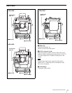
Installation
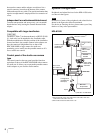
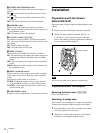
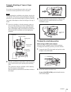
Preparations with the Camera
(HDLA1500/1505)
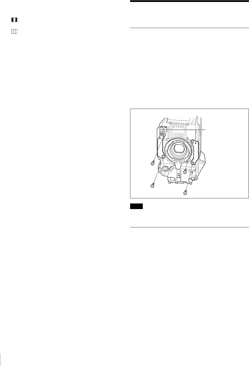
Attach the camera hangers supplied with the adaptor to the
camera.
1
Remove the four blind bushes from the front panel.
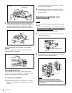
2
Attach the camera hangers (supplied, Part No.: A-
1128-405-A (1 pair)) and secure them to the front
panel of the camera by firmly tightening the +B4
×10
screws supplied with the hangers.
Do not use any other screws than the supplied ones.
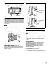
Preparations with the Adaptor
Removing the front cover [1500][1505]
Remove the front cover.
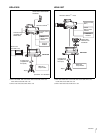
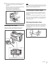
Attaching a V-wedge shoe
If the camera is to be mounted on a tripod, first attach the
V-wedge shoe (supplied with the tripod) to the adaptor.
1
Place the adaptor on its side on a stable stand so that
you have a good view of the base.
2
Attach the V-wedge shoe to the base of the adaptor,
using the screws supplied with the tripod.
Note
Camera hangers