


12
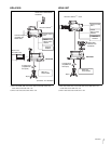
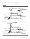
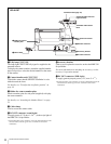
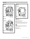
Locations and Functions of Parts
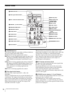
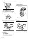
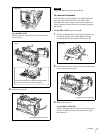
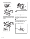
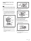
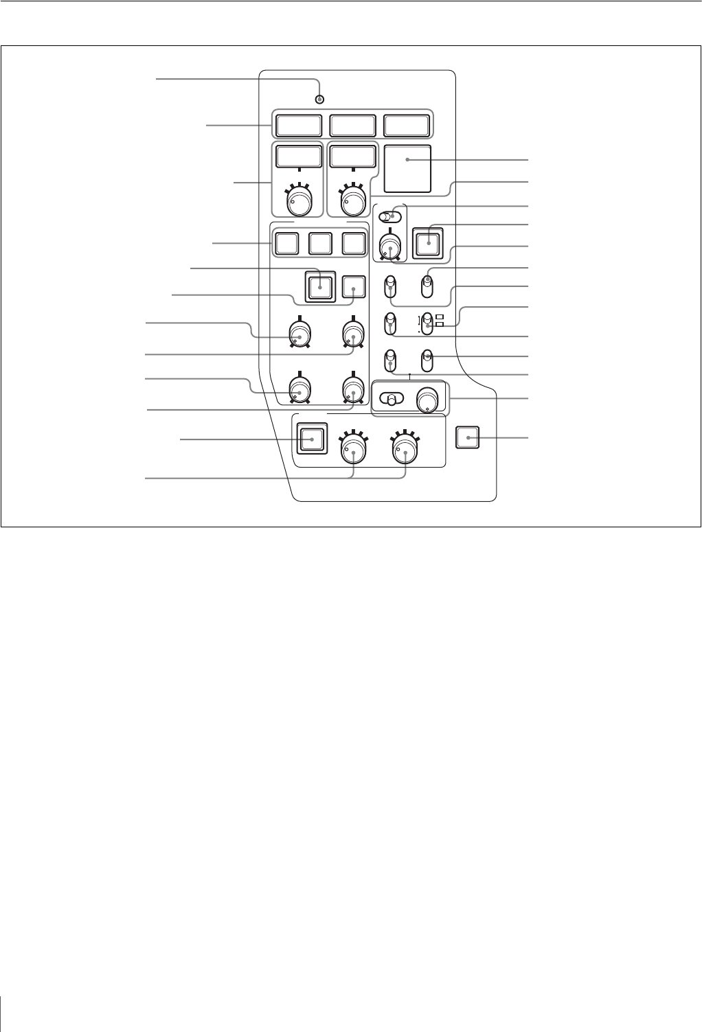
Control Panel
a POWER indicator
This indicator lights up or goes dark as follows to indicate
the power supply status of the camera:
Green: Power is being supplied to the camera.
Red: Power is being supplied to the camera, but the CAM
PW button of the MSU-900/950 Master Setup Unit or
RCP-700/900-series Remote Control Panel is set to
OFF.
Yellow: Power is being supplied to the camera, but the VF
PW button of the MSU-900/950 Master Setup Unit or
RCP-700/900-series Remote Control Panel is set to
OFF, and power is not being supplied to the
viewfinder.
Off: Power is not being supplied to the camera.
b Video signal select buttons
Select the video output signal (R, G, or B) to the
viewfinder.
The R, G, and B buttons may be pressed individually or in
combination. The signal corresponding to each pressed
button will be output. When two buttons are pressed, the
output will consist of those two signals mixed together.
When all three buttons are pressed, the output to the
viewfinder will be the Y signal.
When no buttons is pressed, the output will be a color
signal if the viewfinder is a color model, and it will be the
Y signal if the viewfinder is a monochrome model.
The video output to the monitor connected to the TEST
OUT connector of the camera will also depend on the
setting of these buttons (however, this output is in
monochrome in all situations).
c RET 1 button and selector knob
You may select from among the four return signals from
the CCU, using the selector knob.
By pressing the button, you can view the return video
signal selected by the selector knob, on the viewfinder
screen. Pressing the button again will switch the
viewfinder screen display and monitor output back to the
camera’s video signal.
d CURSOR (cursor memory) 1, 2, and 3 buttons
Used to store the size and position of the box cursor to be
displayed on the viewfinder screen.
Three different box cursor settings can be stored in
memory using buttons 1, 2, and 3. Pressing one of these
buttons will cause a cursor of the respective stored size and
position to be displayed.
1
2
3
4
1
2
3
4
1
2
3
4
5
A
B
C
D
E
R
POWER
RET 1
1 2 3
ON
CALL
RET 2
GB
CURSOR
STORE
H-POSI V-POSI
HEIGHT
ASSIGN-
ABLE
WIDTH
FILTER
LOCAL
VF DTL
OFF ON
ND CC
CANCEL ENTER
MENU
ON
ON
ON
OFF
OFF
OFF
ON 16:9
4:3 OFF
OFF
ON
UP TALLY
DISPLAY
MARKER MARKER
MIX VF
VF SCAN
SCREEN SIZE
aPOWER indicator
bVideo signal select buttons
cRET 1 button and selector knob
dCURSOR 1, 2, and 3 buttons
eCURSOR STORE button
fCURSOR ON button
gH-POSI control
hV-POSI control
iWIDTH control
jHEIGHT control
kFILTER LOCAL button
lFilter selectors
nRET 2 button and
selector knob
oVF DTL switch
pCALL button
rVF SCAN switch
sMIX VF switch
tSCREEN SIZE MARKER
switch
uMARKER switch
vUP TALLY switch
wDISPLAY switch
xMENU switch and control
yASSIGNABLE switch
qVF DTL control
mBack tally lamp