


13
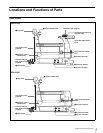
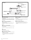
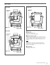
Locations and Functions of Parts
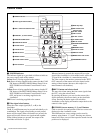
When one of the CURSOR buttons is lit, the H-POSI, V-
POSI, WIDTH, and HEIGHT buttons do not function.
e CURSOR STORE button
Press this button to store the size and position of the box
cursor in memory.
If the CURSOR ON button is not lit, box cursor
information will not be stored.
f CURSOR ON button
When this button is pressed, the button will light up and the
box cursor will be displayed on the viewfinder screen.
When the button is pressed again, the light will go off and
the box cursor will disappear.
g H-POSI (horizontal position) control
Adjust the horizontal position of the box cursor displayed
on the viewfinder screen within the effective resolution
area.
h V-POSI (vertical position) control
Adjust the vertical position of the box cursor displayed on
the viewfinder screen within the effective resolution area.
i WIDTH control
Adjust the width of the box cursor displayed on the
viewfinder screen within the effective resolution area.
j HEIGHT control
Adjust the height of the box cursor displayed on the
viewfinder screen within the effective resolution area.
k FILTER LOCAL (filter local control) button
Pressing and lightening this button enables selecting of a
color temperature conversion filter and ND filter using the
CC filter selector
and ND filter selector. Pressing the
button again (it goes dark) gives control of the filters to the
MSU-900/950 Master Setup Unit or RCP-700/900-series
Remote Control Panel.
l Filter selectors
When the FILTER LOCAL button is lit up, you can change
the ND filter and CC (color temperature conversion) filter
settings.
Turn the left selector to select an ND filter and the right
selector
to select a CC filter.
m Back tally lamp
This lamp lights red when the red tally signal is supplied to
the camera. When the CALL button on the MSU-900/950
Master Setup Unit or the RCP-700/900-series Remote
Control Panel is pressed, the lamp lights if previously off
or goes off if previously on.
You can display the camera number selected on the menu.
n RET 2 button and selector knob
You may select from among the four return signals (1 to 4)
from the CCU using the selector knob.
By pressing the button, you can view the return video
signal selected by the selector knob, on the viewfinder
screen. Pressing the button again will switch the
viewfinder screen display and monitor output back to the
camera’s video signal.
If both the RET 1 and RET 2 buttons are pressed, the RET
1 button takes the priority.
o VF DTL (viewfinder detail adjustment) switch
ON: Emphasizes the contours of the image on the
viewfinder screen. When the switch is set to this
position, you can adjust the amount of detail using the
VF DTL control.
OFF: Disables contour emphasis.
p CALL button
• Press to call the operator of the Camera Control Unit, the
MSU-900/950 Master Setup Unit, or the RCP-700/900-
series Remote Control Panel connected to the camera.
When pressed, the camera’s red tally lamp will light up
if previously off, and turn off if previously on. The
CALL button on the connected control devices will light
up, and their buzzer will sound.
• When the CALL button on a connected control device is
pressed, this button will light up.
q VF DTL (viewfinder detail) control
Adjust the amount of detail of the picture on the viewfinder
screen when the VF DTL switch is set to ON. This has no
effect on the output signal of the camera.
r VF (viewfinder) SCAN switch
Used to control the viewfinder screen display.
16:9: To set the viewfinder display to the 16:9 aspect ratio.
4:3: To set the viewfinder display to the 4:3 aspect ratio.
This switch is enabled on the HDVF-700A only.
s MIX VF (mixture viewfinder) switch
You can see the mixed signal of the camera’s output signal
and the return video signal on the viewfinder screen.
ON: This function is enabled. You can see the mixed signal
of the camera’s output signal and the selected return
video signal on the viewfinder screen when you press
the RET 1 or RET 2 button.
OFF: This function is disabled.
Note
Note
Note
Note