


US Jazzy 1113/Rev I/Feb03 www.pridemobility.com 29
VII. ASSEMBLY
To install the battery well frame:
1. Face the rear of the chair and hold the battery well frame so
that the belly of the well hangs downward.
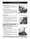
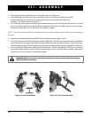
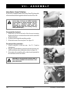
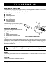
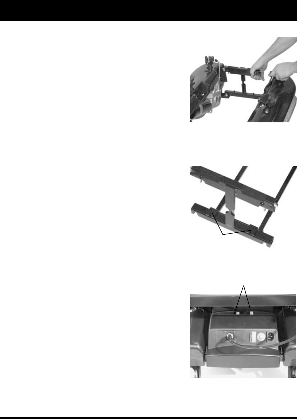
2. Position the notches on the front of the battery well frame onto
the locating pins on the bottom bar of the front frame. See
figure 21.
3. Fit the notch on either side of the rear of the battery well frame
onto the locating pin on the right frame assembly and onto the
locating pin on the left frame assembly.
4. Make certain that the locking mechanisms snap securely into
place.
To install the battery cases:
1. Place the front battery case (with the battery inside) into the
front end of the battery well frame.
Note: Make certain that the connectors are facing toward the
center.
2. Place the rear battery case (with the battery inside) into the
back end of the battery well frame.
3. Make certain that none of the wiring harnesses or cables are
pinched between the battery or the motor controller box and
the frame.
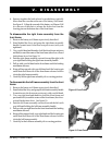
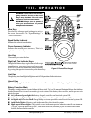
4. Connect the 4-conductor power cable connectors from the
front and rear battery cases to the electronics tray. Push the
connector firmly and fully into the socket. See figure 22.
5. Reconnect the left and right motor connectors to their sockets
located on the left and right frame assemblies. Be certain to
match the left connector to the left motor and the right
connector to the right motor (the connectors are labeled left
and right).
To install the seat:
1. Pick up the seat by the frame itself (not by the armrests) and
slide the locating pins near the back of the frame into the
matching slots on the left and rear seat post tower mounts.
2. Slide the pins to the back of the slots. It may be necessary to
wiggle the seat slightly from side to side to seat the pins firmly
at the back of the slots.
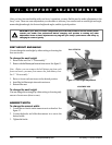
3. Push the front of the seat frame down until both the left and the
right frame sides lock into the front seat post tower mounts.
See figures 23 and 24.
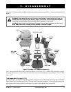
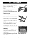
Figure 20. Fitting the Frames
Figure 21. The Locating Pins
Figure 22. Rear Electronics Tray
CONNECTORS
LOCATING
PINS