


22 www.pridemobility.com US Jazzy 1113/Rev I/Feb03
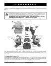
V. DISASSEMBLY
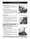
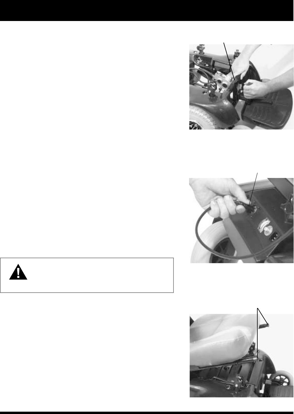
SLIDE FOOTREST UP AND PULL FORWARD TO REMOVE
Figure 5. Remove the Footrest
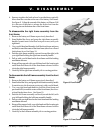
DISCONNECT JOYSTICK CONTROLLER
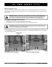
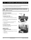
SEAT FRAME LATCH RELEASE BUTTONS
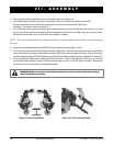
Figure 6. Joystick Controller Harness
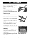
Figure 7. Remove the Seat
To remove the footrest:
1. Remove the footrest by sliding the mounting bracket up the
vertical bar of the front frame until the tabs on the mounting
bracket can be pulled forward through the matching slots in the
front frame. See figure 5.
To disconnect the controller:
1. At the rear of the Jazzy, disconnect the controller harness
connectors from the electronics tray located at the well frame.
You may need to pull firmly and gently wiggle the connector to
remove it from the socket. For the smaller connector, you must
squeeze the connector latch release levers to disconnect the
connector from the socket. See figure 6.
To remove the seat:
1. Disconnect the controller harness connectors as previously
described.
2. Push in the black spring-loaded seat frame latch release buttons
(one on the front of each seat frame side tube). See figure 7.
3. While you are pushing both buttons or levers simultaneously, lift
up on the front end of the seat frame.
4. Pull forward on the seat frame to release the locating pins from
their slots in the rear seat post tower mounts. You may find it
necessary to wiggle the frame gently from side to side to free the
locating pins from their slots.
WARNING
!
Do not pick up the seat frame by the
armrests. They are free to pivot, and you may lose
control of the seat if they do so, resulting in
personal injury or damage to the chair.
To remove the battery well frame:
1. Remove the seat as previously described.
2. Disconnect the battery case connectors (2) from the utility tray.
See figure 8.
3. Next, disconnect and remove the battery cases (with the batteries
in them) from the battery well frame.
4. Disconnect the left motor connector from its matching socket
located on the left frame assembly. Squeeze the connector latch
release levers to disconnect.
5. Disconnect the right motor connector from its matching socket
located on the right frame assembly. Squeeze the connector latch
release levers to disconnect.