


SECTION 9—ANTI-TIPPERS/WHEEL LOCKS
Tracer
®
IV 46 Part No. 1110558
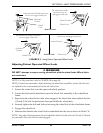
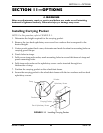
7. RepeattheSTEPS1‐6untilthewheellockshoeembedsthetire1/8‐inch(3/16‐inchfor
pneumatictires)andholdsthewheelchair.
8. Ifthemeasurementof1/8‐inch
(3/16‐inchforpneumatictires)cannot
beachieved,itmaybenecessaryto
installwheellockshoeextensions.
RefertoInstallingWheelLockShoe
Extensionsonpage 46.
9. RepeatSTEPS1‐8fortheopposite
wheellock.
10. Engagebothwheellocksandensure
theoccupiedwheelchairisheldin
placewhenpushed.
ƽ WARNING
If wheel locks DO NOT hold the
occupied wheelchair in place, contact a
qualified technician; otherwise injury or
damage may occur.
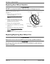
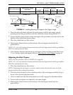
FIGURE 9.4 Adjusting Patient Operated
Wheel Locks
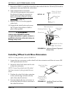
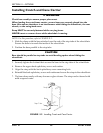
Installing Wheel Lock Shoe Extensions
NOTE:Forthisprocedure,refertoFIGURE 9.5.
1. LoosenthetwosetscrewsonthewheellockshoeextensionuntilthesetscrewsDO
NOTprotrudeintotheslot.
2. Insertthewheellockshoeintotheslot
intheshoeextension.
NOTE:Ensurethepointedendofthewheel
lockshoeextensionisfacingtowardtherear
wheel.
3. Positionthewheellockshoeextension
sotheoutsideedgeisflushwiththe
endofthewheellockshoe.
4. Securelytightenthetwosetscrewsto
securethewheellockshoeextensionto
thewheellockshoes.
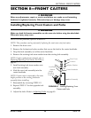
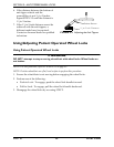
FIGURE 9.5 Installing Wheel Lock Shoe
Extensions
1/8-inch (3/16-inch
pneumatic tires)
Wheel Lock
Shoe
Tire
Wheel Lock
Handle
Rear Wheel
Wheel Lock Shoe
Wheel Lock
Bolt and Locknut
Mounting Positions
DETAIL “A”
Wheel Lock Shoe
Extension
Pointed End of
Wheel Lock Shoe
Extension
Slot
Set Screws