


SECTION 9—ANTI-TIPPERS/WHEEL LOCKS
Part No. 1110558 43 Tracer
®
IV
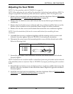
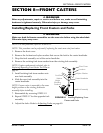
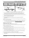
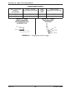
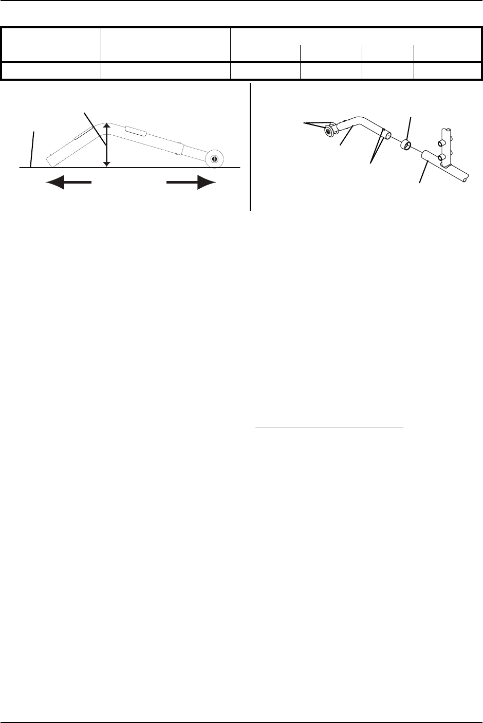
FIGURE 9.1 Installing/Adjusting Anti-tippers - Anti-Tipper Length
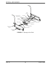
1. Pressthereleasebuttonsandinserttheanti‐tipperswiththeanti‐tipperwheels
pointingtowardtheground/floorintothewheelchairframetubing(Detail“B”).
2. Ensurethatthereleasebuttonoftheanti‐tipperfullyprotrudesoutoftheholeinthe
bottomofthewheelchairframetubing.
3. Placethewheelchaironaflatsurface.
4. Measurethedistancebetweenthebottomoftheanti‐tipperwheelsandthe
ground/floor.
NOTE:A1½to2‐inchclearancebetweenthebottomoftheanti‐tipperwheelsandtheground/floor
MUSTbemaintainedatalltimes.
5. Ifthedistancebetweenthebottomofanti‐tipperwheelsandtheground/floorisnot
1½to2‐inches,adjustanti‐tippers.RefertoAdjustingtheAnti‐Tippersonpage 43.
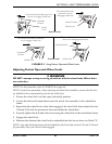
Adjusting the Anti-Tippers
NOTE:Forthisprocedure,refertoFIGURE 9.2onpage44.
NOTE:A1½to2‐inchclearancebetweenthebottomoftheanti‐tipperwheelsandtheground/floor
MUSTbemaintainedatalltimes.
1. Placethewheelchaironaflatsurface.
NOTE:Ifadjustingtheanti‐tippersonreclinermodels,ensurethatthebackcanesareinthe
uprightpositionbeforemakingadjustments.
2. Pressthereleasebuttonsonthewheeledportionoftheanti‐tipperandslideitupor
downtothedesiredadjustmenthole.
3. Checktomakesurethatthereleasebuttonsarefullyengagedinadjustmentholes.
4. Ensurebothanti‐tippersareadjustedtothesameheight.
5. Measurethedistancebetweenthebottomoftheanti‐tipperwheelsandthe
ground/floor.
Wheelchair Model
Seat-to-Floor Height
(in inches)
Anti-Tipper (in inches)
Length Height Model Part No.
TRACER IV 17½ to 19½ 13½ 3¼ 1360 1058836
Anti-Tipper Height
Anti-Tipper
Length
Flat Surface
DETAIL “A”
Anti-Tipper
Wheels
Anti-Tipper
Release Buttons
Rear Frame
Tubing
Anti-Rattle
DETAIL “B”